IP-XACT Design Hierarchy
IP-XACT Design Hierarchy
IP-XACT is an industry standard IEEE 1685-2009/2014 which is recognized by the electronics community as the most appropriate choice for properly and efficiently managing Electronic System Level (ESL) flows. With more complex System Level Designs and IP Components, it is difficult for design and verification engineers to build, integrate, update and verify the design hierarchy. The IEEE 1685 IP-XACT standard was designed to fit this requirement. It not only supports the creation of IP and Design level documents but also provides a mechanism for their interconnection.
What is IPXACT?
IP-XACT describes an EXtensible Markup Language (XML) data format and structure, governed by a schema for capturing the meta-data, which captures the design of intellectual property (IP) used in the development, implementation, and verification of electronic systems.
IP-XACT schema defines a number of document types, and a set of semantic rules that describe the relationships between those documents.
Here are the main document types in IP-XACT:
- Component documents
Component document has several XML tags and attribute that contains IP specific architectural and interconnection information.
Some of those XMLtags are:
- memorymaps:
Memory maps are the addressable area seen by a bus interface. This can be defined for each slave interface of a component. The memoryMaps element contains a unbounded list of memoryMap elements. The memoryMap element are referenced by the component’s slave interface.
- addressBlock:
The addressBlock element describes a single, contiguous block of memory that is part of a memory map.
- registers:
A register element describes a register inside an address block or register file.
- businterfaces:
A businterface is a grouping of ports related to a function, typically a bus, defined by a bus definition and abstraction definition.
- ports:
The ports elements defines an unbounded list of port elements. Each port element describes a single external port on the component. A port element contains a logical port information for a component.
- views:
Views contains a list of all the views for this object. A component may have many different views. Each view can reference a component instantiation, a design instantiation, and a design configuration instantiation. A component instantiation may describe the source hardware module/entity with its pin interface. A design instantiation references an IP-XACT Design representation.
- parameters:
Parameters describes any parameter that can be used to configure or hold information related to the component.
- generators:
Generators are executable objects (e.g., scripts or binary programs) that may be integrated within a DE (referred to as internal) or provided separately as an executable (referred to as external).
- file sets
File sets specifies groups of files and possibly their function for reference by other sections of this component description
- Design documents
Design document contains XMLtags and attribute to describe the architecture of the design (e.g. – instantiation of an IP component inside componentInstances) and configurable parts (e.g.- configurable parameters inside configurableElementValues). Another important part is the interconnections describes how the IP’s inside a Design are connected to each other using bus interfaces or bridges.
- Bus definition documents.
The bus definition document describes a bus type. It describes the signals in the bus interface and the constraints that apply to those signals. This includes signal names, direction, width, and usage. Bus definitions can also describe constrains on the use of that bus type, such as how many bus masters are allowed on each bus.
Abstraction Definition documents.
The abstractionDefinition element contains a list of logical ports that define a representation of the bus type to which it refers.
It is important to understand that IP-XACT XML standard is just a way to represent the structural and transport information of Design and IP. It is a set of plain text files. A good tool which understand this XML standard should be smart enough to import all the described information from a SoC design point of view.
IDesignSpec and SoC Enterprise tools of Agnisys generate all above-mentioned IP-XACT documents corresponding to a Register Specification in both IPXACT 2009 and 2014 editions.

Lorem
IPXACT design structures are very complex, they may contain a long hierarchy chain of many Design and Component (IP or Bus) files. It is hard to manage their corresponding information like their addresses and remap addresses w.r.t to bus and interface interconnections.
Following is an example of a complex SoC design which IDS and SoCe can import easily and can create outputs mentioned above.
ipsum dolor sit amet, consectetur adipiscing elit. Ut elit tellus, luctus nec ullamcorper mattis, pulvinar dapibus leo.

In the above example the System Bus (say AXI) is connected to multiple IP’s using different slave interfaces and with Another Bus (say AHB) with a bridge. IDesignSpec and SoCe can easily import these kinds of Design structures and the address remap information of IP’s w.r.t System Bus.
To import these kind of hierarchy user have to specify the Bus component in IDS using a property {ipxact.buscomp =”Bus component file path separated by comma in case of multiple files”} and to mention top design {ipxact.topdesign =”Path of top design document”}.
Following template shows how to mention these properties –

Lore
SoC Enterprise (SoCe) collects the metadata and converts it to the desired IP-XACT format. User can generate and also import IP-XACT to create its design in SoCe. In SoCe user can provide its information related to a design in following sheets –
Sheets
- General
- Parameters
- I/O Ports
- Interfaces
- Electrical
- Physical
- Enumeration
- Views
- IDS Template
Example of Electrical specification in SoCe:
m ipsum dolor sit amet, consectetur adipiscing elit. Ut elit tellus, luctus nec ullamcorper mattis, pulvinar dapibus leo.

Electrical information described in SoCe goes in vendor extensions of IP-XACT output:

The above IP-XACT can also be converted to graphical view and to other outputs:

SoCe can be used for IP-XACT packaging of a Design specification.
In summary, we have shown how simple and straightforward it is to create and import an IP-XACT description of a Register spec and Design (e.g.- Electrical, Physical and other information) using IDesignSpec and SoCe. In Electronic Design Industry Verification of a design is very important aspect and also it consumes a large amount of time. Under time to market pressure there may be chances that verification engineer may ignore bugs. By using these tools user can save his time by generating “Bug free” precompiled and synthesizable code of various HDL and HVL like Verilog, System Verilog and System-C etc.
Benefits of Automatic Register Verification (ARV™)
Accuracy of Register Verification
Register verification is a significant part of the design verification problem. It is one of the first aspects of the design that must be tested because the rest of the semiconductor functionality depends on the accuracy of the register implementation. That is because registers contain the configuration setting of the hardware and is the basis of the hardware / software interface.
A Verification Engineer has to develop a coverage driven models manually to verify a design. So s/he has to spend a large amount of time in verifying the functionality of a register and memory map of the design. This issue is further exacerbated when there are a large number of IP with registers in an SoC design.
ARV is an application that provides the complete solution for implementing a register verification methodology. The Automatic Register Verification (ARV) module works with IDS. ARV automatically generates the entire test bench, verification plan and Makefiles for complete register verification.
So most of the register verification related problems can be resolved by using ARV.
Rewards of ARV
- ARV Ensures that the Register Implementation, which is either generated automatically or manually created, meets the specification.
- UVM does provide standard register and memory tests like : uvm_reg_hw_reset_seq, uvm_reg_bit_bash_seq ,uvm_reg_access_seq etc. However, these have limitations and give only about 60% functional coverage out of the box. User has to manually put in effort to cover the remaining 40%.
- ARV ensures that the coverage metrics are achieved from all three simulators. ARV also provides make file for all three simulators (Questa/VCS/IRUN). So by using makefile , user can very quickly generate functional coverage as well as code coverage report for every simulator.
- ARV supports testing for special registers like, lock registers, shadow registers, register aliases, interrupts, volatile, sync FIFO etc. It generates sequences for these special registers.
- ARV verifies Memories, Unregistered field and External Hardware component.
- ARV ensures that the application logic correctly interfaces with the registers and memories.
- ARV creates negative tests to verify holes in the memory map.
- ARV generates special tests to cover unexpected behaviors from registers.
- Automatically creates register-focused coverage reports.
- ARV provide a ready-made push-button generation of an entire UVM environment. This can be used as-in or additional sequences for reading and writing can also be added in the environment.
- ARV can import IP-XACT, SystemRDL, RALF, Word, Excel, CSV, XML and host of other formats.
- ARV supports all software access modes for all fields and also the registers with side effects. Examples like – w0t(Write Zero to toggle) , rc (read to clear), ws (write to set), w0crs (write zero to clear and read to set) and many more access are supported in ARV.
- Special tests for Multiple bus domains, async FIFOs and shared registers are also supported*.
Imagine doing all this verification by hand without ARV.
Summary
As mentioned above ARV provides high quality complete register based coverage driven verification environment . ARV automatically generates entire test bench, verification plan ,Makefiles for all three simulator(Questa/VCS/IRUN) so that user can verify design without giving more manual efforts.
Formal verification using ARV-FORMAL
Formal verification using ARV-FORMAL
INTRODUCTION
Formal verification avoids the slowness of event-simulation by using mathematical algorithms and heuristics to prove the functional correctness of a design. Popular specification standards such as IP-XACT , SystemRDL, CSV’s have been used as a starting point for automatically generating any Register Models, RTL, Firmware , and Verification Code . The whole verification process can be further upgraded by automating code for formally verifying IP’s with slave interface , since it helps in reducing simulation efforts and the overhead involved in creating and maintaining block/chip level test-benches. By using directed and constrained random test-cases we may miss out corner cases, which can only be verified formally.
Difference between Simulations based verification and Formal Verification
- Simulation looks at individual points in the space of possible tests, while Formal verification covers that whole space at once.
- The simulation-based methodology is input driven while the formal methodology is output driven.
Formal Verification in IDesignSpec
In IDesignSpec formal verification can be done by extracting a list of properties from specification, each property describes a feature or a property. These properties are further used in formal tools to verify whether they are compliant with the RTL or not.
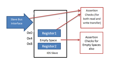
From the specification point of view we have an address space having registers at known addresses and bus interface used in communicating with those registers .

These registers can be formally verified with the bus interface only if the register where the response to bus transaction is taking place at valid address. Assertions properties are also written, for empty address spaces and invalid addresses checking through ARV-Formal.

So for formally verifying an IP we need to know two things
- Bus (Protocol)
- Register /Field ( where there is response to the bus transaction)
- hdl_path is used to specify the name of register or field where there is response to the bus transaction.
- while the bus information is specified in the settings of the Configure Window.
Supported Buses:-
- AMBA-AHB
- AMBA AHB3 LITE
- AMBA-APB
- AMBA-AXI

Example showing Negative testing of register using Assertion Property

Assertion Property generated by IDesignSpec

Types of Assertions Properties Supported
- For a field which is SW readable
a. Whether the data read from the bus is actually being read from the selected field.
b. If the field is readable only, whether writing to it yields an error response.
- For a field which is HW Writable
a. Whether field is getting value form HW Interface.
- For a field which is HW Readable
a. Whether HW interface read the correct field value.
- For a field which is SW writable
a. Whether the data written from bus is actually being written to selected field.
b. If the field is writable only, whether reading from it yields an error response.
- For a block
a. Assertions are written, for empty address spaces and invalid addresses.
b. During reset, if reset value matches the value specified in specification.
c. Assertions for special register/ fields like lock, alias, shadow
Supported Formal Tool
- OneSpin360
- Mentor’s Questa Formal
Summary
Formal verification avoids the slowness of event-simulation by using mathematical algorithms and heuristics to prove the functional correctness of a design. Formal verification systems can also trace back a cone of influence from a safety critical signal or expression in order to prune the code of logic and reduce analysis time. IDesignSpec provides the better solution to it by automatically generating the Assertion checking Properties to reduce the time to market.
Indirect Registers inside Reggroups
Indirect Registers inside Reggroups
In memory mapped digital designs, when you have a limited address space, but you have a need to access a larger memory you use indirect address space. Indirect address space is typically implemented using an index register, a data register and an indirectly addressed memory. IDesignSpec fully supports this scheme in both RTL and UVM.
Recently, we came across a situation where our customers were using the indirect registers inside the reggroups, in addition, the bus width for the direct and the indirect bus was different. This required some specially handling in UVM and RTL. We supported indirect register inside the reggroups with different bus widths.
Using IDesignSpec we can create indirect access of a memory thru two registers – an “index” register and a “data” register. This index-data association is created by adding a property on the data register called “index_reg” and giving it value as name of the Index register.
This one property creates the indirect register access and IDesignSpec automatically creates the RTL, UVM and ARV.
In certain applications the bus communicates directly with a bank of 8 bit registers. There may be another block of wider registers say 32-bit which is accessed indirectly through the 8-bit registers. This can be represented in IDS by the following example –


Here the 8-bit registers (Data0, Data1, Data2, Data3) are grouped together by specifying the property “datagroup = A” on each of them. Where the value “A” is the group name.
The property “indirect_map=Indirect_regmap” is used to specify the indirect registers arrays(32-bit in the indirect map), which is accessed by the index and (Data3 to Data0) data registers in the direct map.
In the UVM Reg Model, the reg_goup is a class extended from uvm_reg_file. Along with index register and data registers, it contains the instantiation of larger memory to be accessed. The Data3 register which is trigger register is configured with the use of index register and larger memory array.
Implicitly a write/read on Data3 triggers write/read to the indirect registers in the indirect_map. You could also explicitly specify properties to trigger read/write to indirect registers by following properties:-
hw_rd_trigger = index, wr
Where a write to the “index” register(8bit) triggers read from the indirect registers (32bit)
hw_wr_trigger=Data3, wr
Where a write to the “Data3” register(8bit) triggers write to the indirect registers (32bit)
The property “datagroup.order= Data0, Data1, Data2, Data3” specifies the order, where Data0 is MSB.
This whole functionality of indirect registers can be tested with the use UVM regModel and Automatic Register Verification(ARV). ARV has special sequences for testing the indirect registers with the corner cases.
Summary
We have shown how easy it is to create indirect registers, inside or ourside reggroups, with same or different buswidths in IDesignSpec. Using these simple properties make the specification very powerful to describe any user scenario. The benefit of automatic RTL, UVM and sequences as a result of these properties is a huge value add and a time saver.


