How To Create Complex Registers in IDesignSpec
We talk about the creation of complex registers in IDesignSpec and the generation of their suitable RTL and UVM models.
The Software addressable registers in your design do not always just have simple read-write access. Sometimes, application demands or implementation constraints require designing them with advanced behavior. Modeling the behavior of these registers in an existing design (RTL) and test bench (UVM) is a challenge and very time-consuming. The time spent verifying these blocks is required since the UVM built-in library tests do not address these additional design features of the register blocks. By combining the automation of the specification through the verification cycle of complex registers, users can benefit from 100 percent coverage and significant time savings since tests are automated.
Also please read the case study of Allegro Microsystems LLC and their use of ARV-Sim™.
With IDesignSpec you could model the behavior of almost all types of complex registers. All you have to do is attach properties on the registers/fields in the IDesignSpec register map specification. This post provides examples of how it is done with the five register types listed below.
Complex registers that can be generated from IDesignSpec are:
- Shadow registers
- Alias registers
- Indirect registers
- Lock register
- RO-WO pair registers at the same address
- And many more
We will cover some of these types in this article and follow up to discuss the rest.
Shadow Registers:
Sometimes, designers may need the register bus (SW access) to automatically copy or shadow data written to a register to another register in the address map. This practice is often employed to facilitate the debugging of designs. A common use case involves checking the content written to write-only registers by reading their corresponding read-write shadow registers. Another scenario is writing to a memory that is shadowed with readable registers.
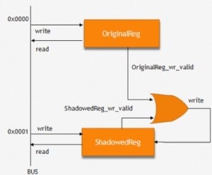
From the figure to the right, we can see that whatever is written to the “OriginalReg” is copied to its shadow register “ShadowedReg”.
So in the design whenever “OriginalReg” is decoded for write, the write valid of the shadow also gets asserted and data is written to the shadow as well.
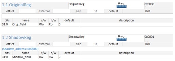
Shadow register representation in IDS Word
In UVM we have implemented this kind of behavior by using callbacks.
class Shadow_cb extends uvm_reg_cbs;
    local uvm_reg_field  m_toF;

    function new(string name, uvm_reg_field toF);
        super.new(name);
        m_toF = toF;
    endfunction

    virtual function void post_predict(input uvm_reg_field  fld,
        input uvm_reg_data_t previous,
        inout uvm_reg_data_t value,
        input uvm_predict_e kind,
        input uvm_path_e path,
        input uvm_reg_map map);
        if (kind == UVM_PREDICT_WRITE && path == UVM_FRONTDOOR) begin
            void'(m_toF.predict(value, -1, UVM_PREDICT_DIRECT, path, map));
        end
    endfunction
endclass
Alias registers
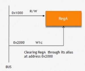
Sometimes a register can have two or more, different views for the software, i.e. it can be accessible from multiple addresses in the same address map. And physically it’s just a single register. Thus a register can have multiple aliases or simply alternate addresses in an address map.
Each of these aliases can have a different access type. For example, fields in a register may be readable when accessed using one address, but write-1-to-clear when accessed from another address. Application logic may use this register to store interrupts. These interrupts can be read by the host bus through the readable address and cleared through the second address.
Another popular approach is to alias only some fields so that they are set/cleared when a particular address is written.
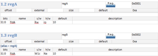
Alias representation in IDS Word
In the UVM model, a callback class for the alias register is created, just like the shadow registers.
The callback is added to the alias registers as shown below.
begin
     Alias_cb Alias_Complex_register_block_regA_Fld1;
     Alias_cb Alias_Complex_register_block_regB_Fld1;
      Alias_Complex_register_block_regA_Fld = new("Alias_Complex_register_block_regA_Fld1", regA.Fld1);
     uvm_reg_field_cb::add(regB.Fld1, Alias_Complex_register_block_regA_Fld1);

      Alias_Complex_register_block_regB_Fld1 = new("Alias_Complex_register_block_regB_Fld1", regB.Fld1);
      uvm_reg_field_cb::add(regA.Fld1, Alias_Complex_register_block_regB_Fld1);
 end
Lock Registers
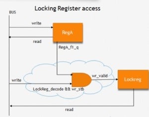
Registers in some designs need to be protected from inadvertent writes. To do that, modal registers may be used. A simple example of a modal register is a “lock” register. Once locked, the protected register disables software writing and functions as a read-only register until unlocked. To lock and unlock register access, one must write a value to another register field or an input signal of the design.
A design design often uses a lock register to control user/supervisory modes. A variant of a lock register is a security register that can be accessed when a complex sequence of writes happens to its address.
Lock representation in IDS Word
In the design, the “write_valid” signal of “lockreg” is dependent on the value of the field “fldA” of the register “regA”.
The UVM callback class for the lock is:
class Lock_field_cb extends uvm_reg_cbs;
        local uvm_reg_field  lock_field;

        function new(uvm_reg_field lock);
            lock_field = lock;
        endfunction

         virtual function void post_predict(input uvm_reg_field  fld,
              input uvm_reg_data_t previous,
              inout uvm_reg_data_t value,
              input uvm_predict_e kind,
              input uvm_path_e path,
              input uvm_reg_map map);
              if (kind == UVM_PREDICT_WRITE) begin
                   if(lock_field.get())
                        begin
                            value = previous;
                         end
                   end
            endfunction
 endclass
The callback class is then added to the register that is to be protected.
RO-WO pair registers at the same address
It is common for registers to have shared addresses within the address map. It’s there in applications like UART, where a register containing write-only fields (WO) shares the same address with another register containing read-only fields (RO, RC, RS). Reading from the shared address gives the content of the Read-Only register and writing to the shared address updates the writeable register.
RO_WO pair in IDS Word
Both registers in the RO-WO pair will be at the same offset and will be decoded at the same time in the design.
In the UVM register model, both registers will be added at the same address in the UVM address map as shown below.
class Complex_register_block_block extends uvm_reg_block;
        `uvm_object_utils(Complex_register_block_block)
        rand Complex_register_block_RX_Register RX_Register;
        rand Complex_register_block_TX_Register TX_Register;
        . . . .
        . . .
       // Function : build
       virtual function void build();
         . . . .
              . . .
            default_map.add_reg( RX_Register, 'h3, "RW");
            default_map.add_reg( TX_Register, 'h3, "RW");
            lock_model();
       endfunction
  endclass : Complex_register_block_block

Indirect Registers
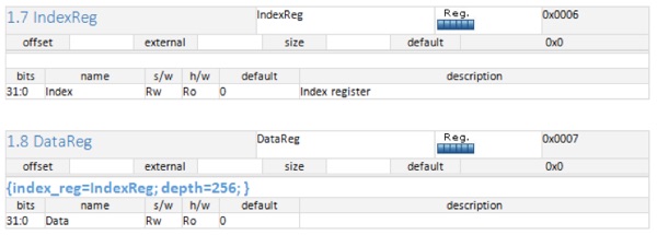
Sometimes due to design constraints registers are not directly accessible via, a dedicated address. To access such registers indirectly, one must first write to an “index” register with a value specifying the array’s offset. A read follows this or write operation of a “data” register to obtain or set the value for the register at the specified offset.
Indirectly addressed registers are used when the available address space is limited.
Representation in IDS Word
In the UVM register model, the indirect registers are modeled as shown below.
class SpecialReg_Data extends uvm_reg_indirect_data;
             `uvm_object_utils(SpecialReg_Data)
             // Function : new
              function new(string name = "SpecialReg_Data");
              super.new(name, 32, build_coverage(UVM_NO_COVERAGE));
              add_coverage(build_coverage(UVM_NO_COVERAGE));
         endfunction
 endclass
…
…
virtual function void build();
 //create
Index   =   SpecialReg_Index::type_id::create("Index");
 foreach (Data_TABLE[_i])
     begin
          Data_TABLE[_i] = SpecialReg_Data_TABLE::type_id::create($sformatf("Data_TABLE[%0x]", _i));     end
  Data   =   SpecialReg_Data::type_id::create("Data");
//config
  Index.configure(this, null, "Index");
   foreach (Data_TABLE[_i])
            begin
                 Data_TABLE[_i].configure(this, null, $sformatf("Data_TABLE[%0x]", _i));
           end
‘ifdef INCA
     begin
             uvm_reg r[256];
            foreach (Data_TABLE[i])
               r[i] = Data_TABLE[i];
              Data.configure(, r ,this, null );
          end
`else
           Data.configure(, Data_TABLE ,this, null );
`endif
//build
 Index.build();
 foreach (Data_TABLE[_i])
        begin
              Data_TABLE[_i].build();
end
Data.build();
//define default map and add reg/regfiles
 default_map= create_map("default_map", 'h0, 4, UVM_BIG_ENDIAN, 0);
default_map.add_reg( Index, 'h0, "RW");
default_map.add_reg( Data, 'h1, "RW");
 lock_model();
 endfunction
Conclusion
This article is all about my experience with the flexibility of IDesignSpec as a tool, which could capture different kinds of complex behaviors of registers in a very simple way. And generate their suitable RTL and UVM model.


