Indirect Registers
How do you create Indirect Registers interface to a slower but wider EEPROM?
In digital design, especially those with area and power constraints, the data and address buses have smaller bus width. One of the direct impacts of the limited address bus width is the limited address space that can be accessed by the design.
When you have a limited address space, but you have a need to access a larger memory, you have only a few options to choose from. You can either address a larger space indirectly, or you can play some games with address paging.
Here we will talk about the first option – using indirect address map and how to implement them in IDesignSpec.
Using IDesignSpec we can create indirect access of a memory thru two registers – an “index” register and a “data” register. This index-data association is created by adding a property on the data register called “index_reg” and giving it value as name of the Index register.
This one property is enough to create the indirect register access and IDesignSpec automatically creates the RTL, UVM and other code snippets for it.
Access to the memory is accomplished by first writing the “index” register with a value that specifies the memory’s offset. Then a read or write of a “data” register to obtain or set the value for the memory at that specified offset.
This is fine when the data width of the direct address space is same as that of the indirect address space. But often that’s not the case and the data bus width of the direct address space is smaller than that of the indirect address space. In this case we need more data registers in the direct address space.
See example below.
In certain applications the bus communicates directly with a bank of 8 bit registers. There may be another block of wider registers say 32-bit which is accessed indirectly through the 8-bit registers. This can be represented in IDS by the following example –

Here the 8-bit registers (Data0, Data1, Data2, Data3) are grouped together by specifying the property “datagroup = A” on each of them, where the value “A” is the group name.
The property “indirect_map=Group1” is used to specify the indirect registers arrays(32-bit in the indirect map), which is accessed by the index and (Data3 to Data0) data registers in the direct map. The value of indirect_map property can be a reggroup name which contains the indirect register array definitions in register templates. This is not a normal regroup, it has a property “virtual = true”, which implies that the registers inside this regroup are excluded from the address map.
Implicitly a write/read on Data3 triggers write/read to the indirect registers in the indirect_map. You could also explicitly specify properties to trigger read/write to indirect registers by following properties:-
hw_rd_trigger = index, wr
Where a write to the “index” register(8bit) triggers read from the indirect registers (32bit)
hw_wr_trigger=Data3, wr
Where a write to the “Data3” register(8bit) triggers write to the indirect registers (32bit)
The property “datagroup.order= Data0, Data1, Data2, Data3” specifies the order, where Data0 is MSB.
You should be careful while using these mentioned properties. As all the properties mentioned here can be used only on data register with “index_reg” property.
In summary, we have shown how simple and straightforward it is to create an “Indirect register” to access external memory using IDesignSpec.
For further information and updates, please refer to the online documentation or send an email to our support team support@agnisys.com.
Creating HW-SW interface FIFO using IDesignSpec
How to setup communication between the host and the application logic?
Invariably modern systems have hardware and software components. The communication between hardware and software is done using a variety of constructs such as registers, memories, interrupts, FIFOs etc. These constructs enable both the domains to send system information to each other.
IDesignSpec (IDS) is a tool to create the memory mapped registers and memories. It can also be used to create interrupt trees and FIFOs. It enables you to create a variety of FIFOs with configurable clock handling, its size and location in memory space, how to deal with thresholds, full/empty flags etc.
Using IDesignSpec FIFO can be created with depth of 2n. The generated FIFO can be written to or read from one of the supported buses such as AMBA-AXI, AHB, APB, WISHBONE, AVALON, and AMBA3AHBLITE. The FIFOs are read-only/write-only or write-only/read-only accesses from Hardware and Software respectively.

Hardware write-only and Software read-only

Software write-only and Hardware read-only
In terms of communication IDesignSpec FIFO also supports simultaneous Read-Write operations. In Verilog RTL, an extra hardware port is generated with the name of the FIFO, also different flags generated for the detection of the state of FIFO –
Empty – this flag shows that fifo is empty and nothing can be read.
Full – it shows that fifo is full and nothing can be written.
Almost_empty – shows that left spaces in fifo is equal to or less than the almost empty value given by user (this flag is only created when you specify the almost empty value by the use of property fifo.almost_empty_val).
Almost_full – shows that occupied spaces in fifo is equal to or greater than the almost full value given by user (this flag is only created when you specify the almost full value by the use of property fifo.almost_full_val).
Following image describes all the Hardware ports generated in IDesignSpec for FIFO –

How we can generate a FIFO using IDS, this can be explained using following example-
You can select FIFO template which resembles with the register template in word-
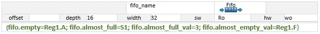
IDesignSpec uses 6 properties for configuring the FIFO, which are mentioned below –
1- fifo.almost_full_val :- used to mention the threshold value
Its value can be
- Any register field
- Any input signal
- Direct value
Please note that if you don’t use this property, almost full flag will not be created.
2- fifo.almost_full :- this property is used to send the almost full flag to any one of the following.
Its value can be
- Any register field
- Any output signal
By default bus error (if sw = wo) or hardware port( if hw=wo)
3- fifo.almost_empty_val :- used to give the threshold value.
Its value can be
- Any register field
- Any input signal
- Direct value
Please note that if you don’t use this property, almost full empty will not be created.
4- fifo.almost_empty :- this property is used to send the almost empty to any one of the following.
Its value can be
- Any register field
- Any output signal
By default bus error (if sw = ro) or hardware port( if hw=ro)
5- fifo.empty :- this property is used to send the empty to any one of the following.
Its value can be
- Any register field
- Any output signal
By default bus error (if sw = ro) or hardware port( if hw=ro)
6- fifo.full :- this property is used to send the full flag to any one of the following.
Its value can be
• Any register field
• Any output signal
By default bus error (if sw = wo) or hardware port( if hw=wo).
In summary, we have shown how simple and straightforward it is to create a FIFO for bidirectional communication between hardware and software using IDesignSpec.
For further information and updates, please refer to the online documentation or send an email to our support team support@agnisys.com.


