IDesignSpec NextGen™
IDesignSpec NextGen™
Behavior-Driven Development (BDD) for IP/SoC
Agnisys has created a new Integrated Development Environment (IDE), which enables users to capture the specification of IP and SoC. The new IDE has no dependency on other editors and no dependency on a particular operating system. IDesignSpec NextGen™ (IDS-NG) is a new technology with Window, linux and Mac based GUI application.
IDS-NG is a purposefully built tool from the ground up for the entire IP/SoC team to capture their design specifications and automatically generate code from it.
Following are some special features of the desktop based GUI application:
- MS Word like tool to create specification on any platform including all version of RedHat, Ubuntu and others, Windows and Mac OS.
- SoC enterprise level, a whole team can collaborate and create IP/SoC.
- Faster speed, with almost 10 times faster than the previous version of IDS.
- Following capabilities of IDS-NG makes it one stop solution for all the problems:
- Creates design specifications
- Error linking to specs are highlighted
- A single UI for capturing all information related to IP/SoC
- Integrated with existing technologies from Agnisys – IDSWord, IDSExcel, ISS and DVinsight.
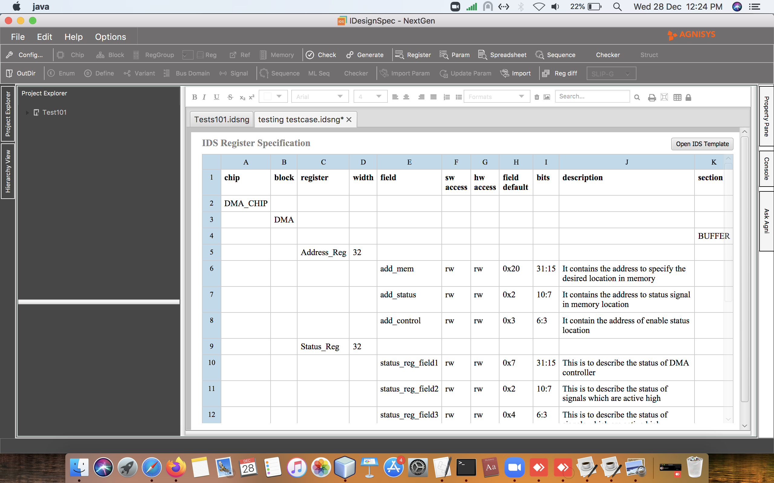
Register Aliasing
Register design and implementation is one of the most important parts of today’s hardware and IC designs. Registers contain the configuration, control setting and status of the hardware and are the basis of the hardware and software interface.
In hardware design, register aliasing describes a situation in which a register location in the hardware design can be accessed through additional symbolic names and addresses. The fields in aliased registers have different access based on the address used. For example, a field in a register may be readable and writable when accessed using one address, but read-only when accessed from another. The hardware access of the alias register is not accessible (NA).
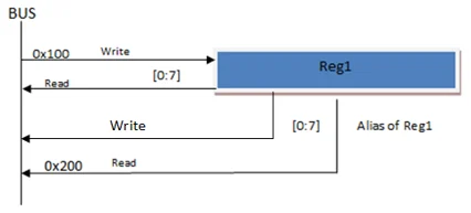
IDesignSpec handles register aliasing in two situations. One is when register locations are in same block address map, as shown in figure 1(a). Other situation is when addresses are in different block address maps, as shown in figure 1(b).
Register aliasing in IDesignSpec:
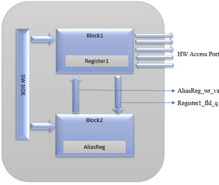
- Register aliasing in same address map:
This is done using the “alias” property which is attached to the register or field that is the alias. The value of this property refers to the Register or the filed that is being aliased.
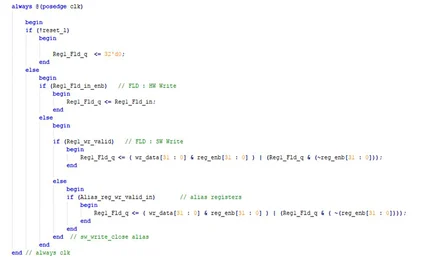
The above-implemented alias property will make the following RTL code:
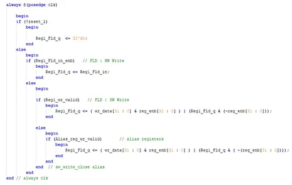
- Register aliasing in different address map:
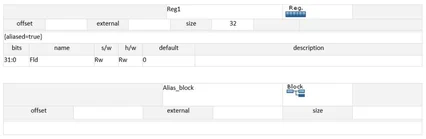
When alias is made across block boundary a new property “aliased = true” is added on the register which is being aliased. The alias property is also used to indicate where the alias register is.
The above implemented alias property will make the following RTL code:
UVM Code:
Alias_cb Alias_Block1_Reg1_Fld;
Alias_cb Alias_aliasBlock_aliasReg1_Fld;
Alias_cb Alias_Block1_Reg2_Fld2;
Alias_cb Alias_aliasBlock_aliasReg2_Fld2;
Alias_Block1_Reg1_Fld = new(“Alias_Block1_Reg1_Fld”, Block1.Reg1.Fld);
uvm_reg_field_cb::add(aliasBlock.aliasReg1.Fld, Alias_Block1_Reg1_Fld);
Alias_aliasBlock_aliasReg1_Fld = new(“Alias_aliasBlock_aliasReg1_Fld”, aliasBlock.aliasReg1.Fld);
uvm_reg_field_cb::add(Block1.Reg1.Fld, Alias_aliasBlock_aliasReg1_Fld);
Alias_Block1_Reg2_Fld2 = new(“Alias_Block1_Reg2_Fld2”, Block1.Reg2.Fld2);
uvm_reg_field_cb::add(aliasBlock.aliasReg2.Fld2, Alias_Block1_Reg2_Fld2);
Alias_aliasBlock_aliasReg2_Fld2 = new(“Alias_aliasBlock_aliasReg2_Fld2”, aliasBlock.aliasReg2.Fld2);
uvm_reg_field_cb::add(Block1.Reg2.Fld2, Alias_aliasBlock_aliasReg2_Fld2);
Usage:
As an example, Alias Register is used in MPU(memory Protection unit).The reason to use this is to allow multiple MPU regions to be accessed and programmed in one instruction, such as store-multiple (STM), to save time and speed up the execution of the programs.
Conclusion:
Alias register is very important in terms of writing specs for industry use and making the process faster resulting in timely execution of the specs. Alias can be made between registers within one block and between registers located in two separate blocks as well, making it even more versatile.
Format property in IDS/ISS
Format property implementation for IDS/ISS
Introduction
Normally only integers are represented in fixed point numbers. This implicitly means that the decimal point is at the right most corner of a number. Also, integers can be signed (2’s complement) or unsigned. However, in Math intensive applications, fixed point numbers can also be used to represent real numbers. In this case the decimal point moves towards left of the number.
A new property is introduced called “format”. Its value will be of the form “fixdt(,,)”. This property constructs fixed-point numeric values from real values. It works in the similar manner as the “fi” function used in MATLAB, to construct fixed-point numeric object.
The integer value is calculated using the following formula –
Real value = (Integer value) x 2(-fractional bits)
In case the calculated Integer value is bigger than the field length, of register field on which the “format” property is applied, then the integer value saturates to the field length.
Eg: “{format=fixdt(1,,5)}”, applied on the register field of length ‘8’ and having value ‘30.5’, with ‘5’ fractional bits, returns value 127. From the above formula the integer value comes out to be ‘976’ but as the field length is only ‘8’ including the sign bit, so, the returned integer value saturates to (27 – 1) i.e. ‘127’.
The value of fractional bits can be negative also. It can also be greater than the length of the field. The integer value is calculated in the same manner described above. Eg:
- “{format=fixdt(0,,-3)}”, applied on the register field of length ‘9’ and having value ‘100.1’, with ‘-3’ returns value ‘13’.
- “{format=fixdt(1,,10)}”, applied on the register field of length ‘7’ and having value ‘0.0048725’, with ‘10’ returns value ‘-5’.
Implementation
Proposed “format” property can be defined on register fields in ISS sequence sheet or on the register fields in the IDS document, if format property is defined on a field both in the IDS document and sequence sheet then, one on the sequence sheet takes precedence. A user can define a real value, in following manner using format property.
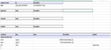
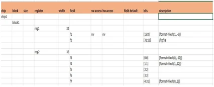
Eg: {format=fixdt (0,,3)}, where ‘0 ‘is the sign value and ‘3’ is the fractional length. The word length will be the field length of the corresponding field on which the property is defined, i.e. 16 (as reg1.f1 is defined from [15:0] in IDS/ISS as shown below)
{format= fixdt(1,,-5)}, where ‘1 ‘is the sign value and ‘-5’ is the fractional length. The word length will be the field length of the corresponding field on which the property is defined, i.e. 16 (as reg1.f2 is defined from [31:16] in IDS/ISS as shown below)
Conclusion-
With the use of format property, we are able to represent real numbers in fixed point numbers along with the integers, which was not supported earlier. By doing this, we have successfully supported the MATLAB’s ‘fi’ functionality, to construct fixed-point numeric object.
I2C Supported in IDS
IDS now supports the Serial interface via the I2C bus protocol. Various operating modes are implemented.
It contains the I2C-bus data transfer, handshaking and bus arbitration schemes. I2C widget is implemented for 7 bit addressing mode as user will specify the address of the device as slave address. Which will be user specified. 8-bit register address is supported for read and write the data. The I2C widget will take data into I2C format from I2c Master device and converts it to proprietary interface.
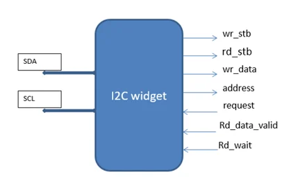
i2c with IDS internal signal connections
User can easily communicate with IDS serially using I2C master from the host (software) side. There are some initial configurations before starting with I2C: IDS provides a way to configure these initials at the beginning itself. It provides the user with configurable bus select option, I2C then selects device addressing mode and slave address.
The I2C provides an interface between the Master and other devices compliant with Philips Semiconductors Inter-IC bus (I2C-bus) specification version 2.1 and connected by way of an I2C-bus.
Most TI devices (c5000, c6000, OMAP, Davinci, etc.) use the underlying modules.
Supported Bus Features
- Compatible with Philips I2C Standard. Only two bus lines are required; a serial data line (SDA) and a serial clock line (SCL).
- Single master operation
- Software programmable clock frequency, Generally 3 Transmission speeds: Normal, Fast, and High Speed.
- Clock stretching and wait states generation.
- Software programmable acknowledge bit.
- Interrupt or bit polling driven for each byte.
- Start, Stop, Repeated Start detection.
- Supports 7 bit with configurable address masking in slave mode.
- Supports strict I2C reserved rule, Detects general call addresses.
- Support for IDS compatible byte format transfer for Register address.
- Bus busy detection.
i2c with IDS internal signal connections
The I2C Widget provides an interface between I2C Slave (A Two wire information) and IDS internal signals. This widget can be used at software side of the IDS and provides a way of introducing serial communication channel for the clients.
FSM Diagram for I2C Widget
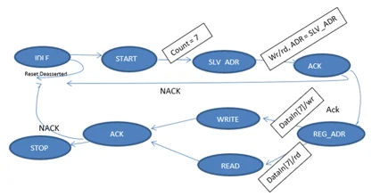
A finite state machine for I2C controller
7-bit Slave Address and RD/WR bit Format
After the START condition (S), a slave address is sent. This address is seven bits long followed by an eighth bit which is a data direction bit (R/W) — a ‘zero’ indicates a transmission (WRITE), a ‘one’ indicates a request for data (READ).
A data transfer is always terminated by a STOP condition (P) generated by the master. However, if a master still wishes to communicate on the bus, it can generate a repeated START condition (Sr) and address another slave without first generating a STOP condition. Various combinations of read/write formats are then possible within such a transfer.
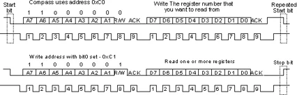
A complete Data Transmission by I2C
Configurable Addressing
IDS provide a facility to configure 7-bit addressing of a particular device before start generation of I2C Interface with IDS. This addressing follow all the rules and regulations complaint with Philips Semiconductors Inter-IC bus (I2C-bus) specification version 2.1.
8-bit of Register Address:
After the slave address is acknowledged, user needs to send a byte that is a specified IDS register address which is byte addressable by the increment of four bytes for each register.
If there is a memory specified, this controller will take care of an appropriate address calculation or an offset value compatible with IDS requirements.
Because the default address of an IDS registers is 32 bit, widget will split this address into separate bytes which are followed by one after the other covering the full register by using repeated Start logic.
Summary
In addition to I2C we have also supported the SPI bus. Please contact support for access to these widgets and latest executable with the new support.
Apache Velocity Template
Apache Velocity Template
Introduction
IDesignSpec (IDS) introduces its new feature which enable users to customize and create their own outputs using Velocity template- main benefit of using Apache Velocity Template. It enables user to create fast and personalized outputs.
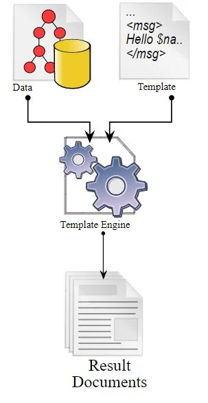
Our Velocity template is based on a very simple architecture with two components – a data model and the template. This data model is basically the input IDesignSpec file which describes the design specification. Input file can be of any format which is supported by IDesignSpec example: SystemRDL, IP-XACT, Word, Excel, RALF, etc. The other component is the Template, which is defined and designed by the user. The template is a plain text file that describes the static output and dynamic elements from the data model.
To design this template, we provide several handy commands, like, $ids.get_system, $ids.get_board, $ids.get_chip, $ids.get_object_by_name, $ids.get_top, $ids.get_prop, etc. Also, it is totally Java based, so mostly all the functions of Java langauge works in here. The Template Processor processes both Data model as well as Template to provide the user with required output.
Here, “Templates” in IDS documents translates into “Objects” in Velocity template. The Velocity Application Programming Interface introduces seven object types, each corresponding to a document template. The following types of objects have been introduced in the Velocity API of IDS:
- System
- Board
- Chip
- Block
- RegGroup
- Reg
- Fields
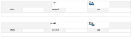
For example, property / value pairs on the templates translate into ‘properties’ within objects. So for a “block”, the value specified for offset can be accessed by getting the ‘offset’ property of the block object in velocity Template.
Example-
Here is a sample that illustrates the usage of Velocity Templates. It shows the design specification, the velocity template and the generated output.
- Design Specification
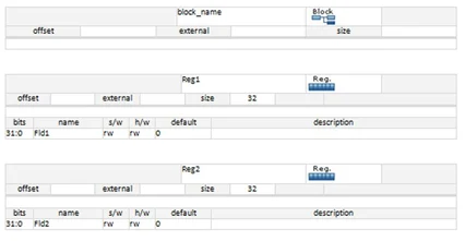
- Velocity Template
#set($put=”include”)
#set($top=$ids.get_top())
#$set “global_types.h”
#$set “global_registers.h”
#foreach($child in $ids.get_objects($top))
/****************************************************************************
* VARIABLE Data structure of register $ids.get_prop($child,”name”) in
* component instance $ids.get_prop($top,”name”)
****************************************************************************/
BW_register_info_t $ids.get_prop($top,”name”)__$ids.get_prop($child,”name”) = {
“$ids.get_prop($child,”name”)”,
$ids.get_prop($child,”offset”),
$ids.get_prop($child,”default”),
$ids.get_prop($child,”size”)
};
#end
/****************************************************************************
* VARIABLE reg_info
****************************************************************************/
const BW_register_info_t *BW_reg_info[] = {
#foreach($child in $ids.get_objects($top))
#if($comma==1),#end&$ids.get_prop($top,”name”)__$ids.get_prop($child,”name”) #set($comma = 1)
#end
};
- Command-
idsbatch <input_file> -velocity <velocity_file>
- Output-
#$set “global_types.h”
#$set “global_registers.h”
/****************************************************************************
*
* VARIABLE Data structure of register Reg1 in
* component instance block_name
****************************************************************************/
BW_register_info_t block_name__Reg1 = {
“Reg1”,
0,
0x00000000,
4
};
/****************************************************************************
*
* VARIABLE Data structure of register Reg2 in
* component instance block_name
****************************************************************************/
BW_register_info_t block_name__Reg2 = {
“Reg2”,
4,
0x00000000,
4
};
/****************************************************************************
* VARIABLE reg_info
****************************************************************************/
const BW_register_info_t *BW_reg_info[] = {
&block_name__Reg1 , &block_name__Reg2
};
Conclusion-
Apache Velocity Template is a vital feature for personalizing the outputs in the user desired format. Along with this, it is faster. It opens up the possibility for the user to generate any desired output.
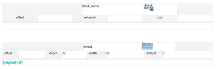
Repeat on Memory
Repeat on Memory
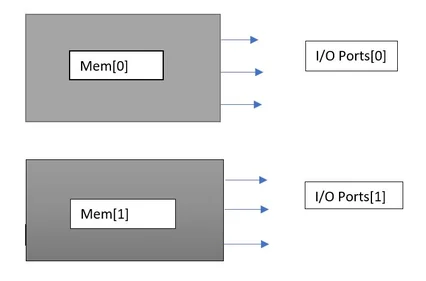
A memory is a storage with contiguous address locations. As the increasing integration density of various IPs into the SoC, the memory system becomes a dominant role to determine the final performance, area, and power consumption of SoC. Different memory templates are required in IDS to have different interferences of memory currently, but if the size of memory is same and different interferences with different ports are required then ‘repeat’ property on memory template can be used.
LOGIC DIAGRAM:
Verilog Code
parameter Mem1_count = 2; //number of memory repeat
generate //generate block for each repeat value
genvar Mem1_i;
for (Mem1_i = 0; Mem1_i < Mem1_count; Mem1_i = Mem1_i + 1)
begin: Mem1_gen
assign Mem1_offset[Mem1_i] = (block_offset/’h80) + ‘h0 + Mem1_i;
assign Mem1_decode[Mem1_i] = (address [(addr_width – 1):7] == Mem1_offset[Mem1_i] [(addr_width -7) – 1: 0])? 1’b1: 1’b0;
assign Mem1_wr_valid[Mem1_i] = Mem1_decode[Mem1_i] && wr_stb;
assign Mem1_rd_valid[Mem1_i] = Mem1_decode[Mem1_i] && rd_stb && rd_wait_state;
assign Mem1_wr_valid_out[Mem1_i] = Mem1_wr_valid[Mem1_i];
assign Mem1_rd_valid_out[Mem1_i] = Mem1_rd_valid[Mem1_i];
assign Mem1_rd_data[Mem1_i] = Mem1_rd_ack_in[Mem1_i] ? Mem1_rd_data_in [(bus_width * (Mem1_i+1)) -1: (Mem1_i * bus_width)]: 32’b00000000000000000000000000000000;
end
endgenerate
UVM Code:
class block_name_block extends uvm_reg_block;
`uvm_object_utils(block_name_block)
rand block_name_Mem1_Mem1 Mem1[2]; //repeat value of memory in the block
virtual function void build();
foreach (Mem1[Mem1_i])
begin
Mem1[Mem1_i] = block_name_Mem1_Mem1::type_id::create($sformatf(“Mem1[%0x]”, Mem1_i));
Mem1[Mem1_i].configure(this, $sformatf(“Mem1[%0x]”, Mem1_i));
end
foreach (Mem1[Mem1_i])
begin
default_map.add_mem(Mem1[Mem1_i], ‘h0 + Mem1_i * ‘h80, “RW”);
end //build() and map() function for each repeat value
USAGE:
The Memory Subsystem is an important component in uniprocessor and multiprocessor systems. It consists of temporary storage that is managed by hardware (cache) or software (scratchpad), as well as more permanent storage that is volatile (main memory) or non-volatile (Flash memory, disk, etc.). It consists of on-chip storage as well as off-chip storage
CONCLUSION:
Repeat on memory is a very convenient feature if we are prepared to interface multiple memories of same size with different ports. In such cases, the repeat property turns out to be extremely handy. Instead of using multiple IDS memory templates, we can use only one template and repeat it as many times as required.