IP-XACT vs SystemRDL: Construct Comparison for Registers

Since its first release in 2010 by the SPIRIT consortium (now Accellera), IP-XACT has become the de-facto format for structuring, packaging, integrating and reusing IPs within tool flows. One of the key reasons for its wide-adoption is its XML-based vendor-neutral format favorable to IP suppliers. IP-XACT can also describe components for memory and register maps, but quite limited in this area, especially as new types of register designs are needed to meet new requirements of next-generation SoCs. To address these limitations, SystemRDL was also formulated by the same industry. SystemRDL is a description language specifically for describing registers to address the growing design complexity.
What is IP-XACT?
This standard provides the EDA vendors, IP providers, and SoC design communities with a well-defined and unified specification for the meta-data that represents the components and designs within an electronic system. This specification enables delivery of compatible IP descriptions to improve the importing and exporting of complex IP that bundles to, from, and between EDA tools for the SoC design environments.
As part of design-build, generators may be provided internally by a system design tool to achieve the required IP integration or configuration, or they may be provided externally and launched by the system design tool as and when desired.
What is SystemRDL?
SystemRDL supports the full project cycle of registers from the specification, model generation, and design verification to maintenance and documentation. SystemRDL minimizes the problems encountered in describing and managing registers. Typically, in a traditional environment, the system architect or hardware designer creates a functional specification of the registers in a design. This specification is then used by other members of the team including software, hardware, and design verification. Each of these parties uses the specification to create representations of data in the languages which they use in their aspect of the chip development process.
During these verification and validation processes, bugs are often encountered which require the original register specification to change. When these changes occur, all the downstream views of this data have to be updated accordingly. This process is typically repeated numerous times during chip development. In addition to the normal debug cycle, there are two additional aspects that can cause changes to the register specification. First, marketing requirements can change, which require changes to a register’s specification. Second, physical aspects, such as area and timing constraints can drive changes to the register’s specification.
These challenges often result in a low-quality product and waste of time due to incompatible register views. Through the application of SystemRDL and a SystemRDL compiler, users can save time and eliminate errors by using a single source of the specification and automatically generating any needed downstream views.
Comparison
Since registers can be described in the textual format using these two industry standards, we often get questions about the pros and cons of each. In this article, we compare and contrast both IP-XACT and SystemRDL
There are many constructs in SystemRDL and IP-XACT to describe the registers. Table 1 shows a basic comparison between them.
Table 1: Comparison of Basic Constructs
| IP-XACT 2014 | SystemRDL |
| <ipxact:memoryMap> | addrmap |
| <ipxact:addressBlock> | addrmap |
| <ipxact:addressOffset> | <block name>
<block_instance> @offset |
| none(can be handled with the help of vendor extension) | external |
| <ipxact:width> | regwidth |
| <ipxact:registerFile> | regfile |
| <ipxact:addressOffset> | <regroup name> <regroup_instance>@offset |
| <ipxact:register> | reg |
| <ipxact:name> | reg <register_name> |
| <ipxact:addressOffset> | <reg name> <reg_instance>@offset |
| <ipxact:volatile> | hw=wo/rw |
| <ipxact:reset> | default |
| <ipxact:description> | desc |
| <ipxact:field> | field |
| <ipxact:bitOffset> | [Lsb] |
| <ipxact:bitWidth> | [Msb : Lsb] |
| <ipxact:access> | sw |
| <ipxact:dim> | [<repeat_value>] |
| Vendor Extensions | User Defined Properties |
| none | Documentation artifacts |
Table 2 shows an implementation of a Lock Register in IP-XACT and SystemRDL. A Lock Register is a register whose software read and write access functionality is locked on another register field or based on an expression consisting of different register fields or some external signal.
Table 2: Comparison of Implementation of Lock Register
| Lock Register Description in IP-XACT | Lock Register Description in SystemRDL |
| <spirit:register>
<spirit:name>lockRegisterWrite</spirit:name> <spirit:addressOffset>0x8</spirit:addressOffset> <spirit:size>32</spirit:size> <spirit:volatile>true</spirit:volatile> <spirit:reset> <spirit:value>0x00000000</spirit:value> <spirit:mask>0xFFFFFFFF</spirit:mask> </spirit:reset> <spirit:field> <spirit:name>Fld3</spirit:name> <spirit:bitOffset>0</spirit:bitOffset> <spirit:bitWidth>32</spirit:bitWidth> <spirit:access>read-write</spirit:access> <spirit:vendorExtensions> <ids:default_value>00000000000000000000000000000000</ids:default_value> </spirit:vendorExtensions> </spirit:field> <spirit:vendorExtensions> <ids_properties> <lock>locker.Fld</lock> <address>0x08</address> </ids_properties> </spirit:vendorExtensions> </spirit:register> | property lock { type=string; component = reg|field;};
addrmapblock_name { name = “block_name Address Map”; // Signals signal { activelow; sync; signalwidth = 1; desc= ” This signal is sync and activelow with width 1″; } Sig1; .. .. reg locker { regwidth = 32; field { hw = rw; sw = rw; } Fld[31:0] = 32’h0; }; .. .. reglockRegisterReadWrite { lock = “locker.Fld, wr” ; regwidth = 32; field { hw = rw; sw = rw; } Fld4[31:0] = 32’h0; }; reglockRegisterSignals { lock = “Sig1, wr” ; regwidth = 32; field { hw = rw; sw = rw; } Fld2[31:0] = 32’h0; }; lockRegisterReadlockRegisterRead @0x00; locker locker @0x04; lockRegisterWritelockRegisterWrite @0x08; lockRegisterReadWritelockRegisterReadWrite @0x0C; lockRegisterSignalslockRegisterSignals @0x10; }; |
IDesignSpec supports both SystemRDL and IP-XACT. It can take both SystemRDL and IP-XACT as an input format and automatically generate various outputs from it such as RTL, UVM Register Model, C Headers, HTML and PDF Documentation. IDesignSpec can also generate SystemRDL and IP-XACT as outputs from various types of inputs for register specification.
This article showed a comparison between IP-XACT and SystemRDL for register descriptions. To capture the design intent at the IP level, IP-XACT can, of course, be used. If the specification contains different types of common and special registers with various features and properties, SystemRDL would be a better choice. Next time, we will look closely on the advantages of IP-XACT vis-a-vis’ SystemRDL.
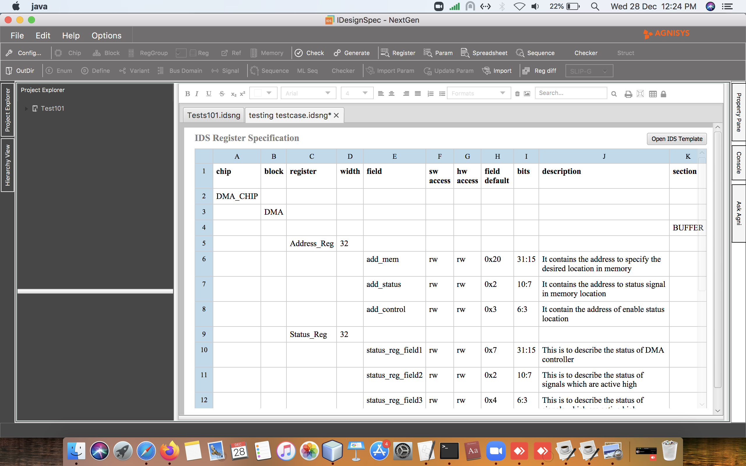
Creating Top Level Registers Specification for an SoC
An SoC is a highly-integrated circuit that typically contains multiple sub-systems that consist of CPUs, GPUs, Memory, Wi-Fi and Display Controllers. When it comes to design and verification of SoC registers and memory maps, one of the best-practices in IDesignSpec is to employ a hierarchical approach in defining the SoC sub-systems and components as Board, Chip, Blocks, and Sub-blocks. This saves a lot of time and helps avoid many headaches during verification.
To understand, let’s start from the very basic block diagram shown in Figure 1. Board 1 references Chip 1, 2 and 3. Chip 1, 2 and 3 all consist of Block 1, 2 and 3.

Fig2. Working of External Descriptor
Register map of DMA will contain only one register (start_de) which will point to the start location of the descriptor/external memory. So, the CPU will only configure this register once and the rest of the transfers will be carried out by DMA itself.
start_de: Starting address of the descriptor (block_offset + 0x0; 32-bit wide)
Figure 2
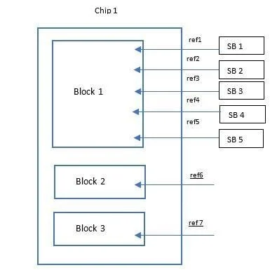
Figure 3
IDesignSpec also has an option to generate hierarchical HTML files from the top-level specification. By default, a flat level single HTML is generated but if a command line option -if or -if_html is given on the command line, hierarchical HTML files are generated. Currently, hierarchical HTML is generated only if htmlalt2 is chosen as one of the outputs. This is very useful for large SoC datasheet generation.
Given below is a sample idsbatch command-line which can be used at the top level to generate UVM and HTML outputs:
idsbatch ABC level.xlsx -sheet_name Board -no_formatting -output “uvm htmlalt2” -out_third_party d -hdlpath -coverage -addr_sort -if -top_property “global_addressing=true;uvm_lock_model=false;uvm.base_class=mvm_reg_block;vertical_reuse=true” -preserve -velocity “board:/cde/cad/tools/agnisys/idsbatch/template/%board%_regdef.svh.vm board:/cde/cad/tools/agnisys/idsbatch/template/%board%_struct.svh.vm chip:/cde/cad/tools/agnisys/idsbatch/template/%chip%_regdef.svh.vm chip:/cde/cad/tools/agnisys/idsbatch/template/%chip%_struct.svh.vm block:/cde/cad/tools/agnisys/idsbatch/template/%block%_regdef.svh.vm block:/cde/cad/tools/agnisys/idsbatch/template/%block%_struct.svh.vm”
This article explained us a detailed view of creating a top level register specification for an SoC. It further explained various properties in IDesignSpec and how they could be used to create register specs at the top level for an SoC.
How to speed-up the UVM register model
While working on small separate block-level verification environments, it is easy to manage any performance issues that originate from the UVM register model. However, when validating a large SoC the UVM register model, the coding methodology can have a huge performance impact, and can often become the bottleneck during system-level simulations.
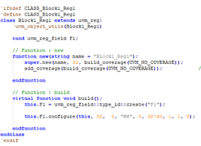
Since each UVM register model contains a field, register and hierarchical block defined by classes, we often end up having a lot more System Verilog classes in the register model than the rest of the verification environment – this consequently affects the performance. It is customary to use the uvm_object_utils to register the user-specified field classes and registers with the UVM built-in factory, and then use the factory’s create() method instead of constructing directly using the new() function. However, if our use-case does not involve using any features of the factory and we have many register model classes, then using the factory seems unnecessary. In fact, the UVM register model will function correctly without uvm_object_utils. A similar register definition can be achieved by removing the uvm_object_utils macro and replacing the corresponding type_id::create methods with a direct call to new() method for fields and registers, deprecating the factory for this aspect of the verification environment operation.
In the latest release of IDesignSpec, a new property has been introduced which helps users save time and improve the register model code performance. We have implemented IDS property {uvm_opt=1} at the top level to speed up the UVM register model. By using this property IDesignSpec removes the UVM factory registration of macros, and it is hierarchical in nature.
- E.g.: uvm_object_utils which are used to register UVM objects and UVM components respectively with the factory. Instead of UVM factory create() in build function, it will use new() for UVM optimization.
As an example, the following code below has been generated from IDesignSpec without using the property uvm_opt = 1.
intr_enable: Interrupt Enable Register (block_offset + 0x1c; 32-bit wide)
Depending upon the generation parameter this register can be replaced by an interrupt mask register.
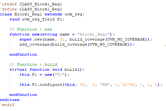
Figure 2: Code generated by using property uvm_opt =1
As a summary, this new property makes the entire process more efficient and improves the performance of the UVM register model.
Efficiently Manage Multiple Top-Level Designs with Aggregation Logic
Today’s electronics consumers demand more and more peripherals within their devices – that’s really good for the consumers, but problematic for SoC design and verification teams. The increasing number of peripherals entails a large number of internal I/O ports within the SoC which presents painful challenges in managing multiple top-level designs. It also entails changes in the working fully-scripted flow which consequently results to more bugs that need to be mitigated prior to tape-out.
In order to zero in on various types of bugs, often design and verification teams need to work on different modules at the same time. This makes it cumbersome and difficult in switching from one design to another placed at different locations. A huge amount of manual intervention is needed to create an environment for separate modules and is definitely time-consuming.
To resolve these challenges – IDesignSpec provides a modular approach for managing multiple top-level designs by applying an aggregation logic with the RTL Wrapper – enabling the user to automatically generate a clustered environment for multiple top-level designs and navigate through them seamlessly when needed. The comprehensiveness of the automated code generation process is what separates IDesignSpec from competing tools, this new feature has been added to this automated process making the capabilities even stronger.
In our previous articles, we discussed the RTL Wrapper property which provides the interface between the register RTL block generated by IDesignSpec and the custom programmable logic (user’s secret sauce) created and managed outside IDesignSpec.
IDesignSpec enables users to generate an aggregation logic around the automatically generated RTL code with the RTL Wrapper. As shown in Figure 1, the aggregation logic brings together the block components inside the design and allows the user to navigate through them. It employs the slave and based on the input from the master it selects the block to be operated. It combines multiple modules by instantiating them into a single unit for performing tasks over it. The bridge between the bus and the RTL block improves the modularity of the design to a great extent by combining different modules together. The aggregation logic accepts the address from the master bus and decodes the address based on the automatically generated address provided by IDesignSpec. The accepted address from the bus if lies between the automatically generated address space enables the pin connected to that address.
The RTL Wrapper along with aggregation logic act as an absolute driver for the RTL. Using them together enables the designers to create a complete infrastructure for multiple top-level designs.

Fig 1: Aggregation Logic incorporated in the RTL Wrapper
Advantages of using RTL Wrapper along with Aggregation Logic
- Provides efficient controllability to the user in switching between different modules clustered inside the aggregation logic
- Makes the generated design more compact with increased modularity of the code
- Automatically generates an environment which interacts between the custom programmable logic, master and generated RTL block
- Reduction of manual steps, fast and automated, thus eliminating the danger of bugs
- Flexibility to specify additional pins along with registers
- Provides more feasibility and reusability for the user
- Reduces the routing resource requirements
- Helps meet the timing for the bus signals
This article illustrated an efficient approach to manage multiple top-level designs with Aggregation Logic. It further explained the advantages of using RTL Wrapper along with aggregation logic.