Dynamic ‘Next’ Input Assignment With Events
IDesignSpec™ (IDS) has grown in terms of capacity and performance over the years. With new added features and enhancements in existing flow keeping backward compatibility intact, it has matured and diversified further in terms of functionality support.
The ‘next’ property is used for assigning the next input value on the defined field bits of a register that can be either the value of a signal from the hardware interface or the value of any other defined field of a register within the scope of the register specification.
For example, the property can be applied as below on a field component (i.e., grouped bits of a register):
- For a signal s1 from the hardware interface
e.g., next = s1 - For any other field of same width in the IDS block
e.g., next = <some_reg>.<some_field>
This property has been further enhanced to support:
- Conditional assignment of the next input value with respect to events of the software interface
These events can be read/write events from the bus interface on any other internal register address of the IDS block.
- Dynamic assignment on specific iterations of a repeated parent component of the register field bits
A field of a specific component among an array of components can be assigned a next input value for updating field bits in the next cycle. In cases where repeat on both parent register and ancestor section component is used to assign a dynamic next value, the repeat on immediate parent is considered for assigning the value.
- Two-way assignment between fields within a single IDS block
Two register fields in the same IDS block can be assigned each other’s value based on each other’s software read/write events as the next input value.
EXAMPLE CASE (two-way next assignment)
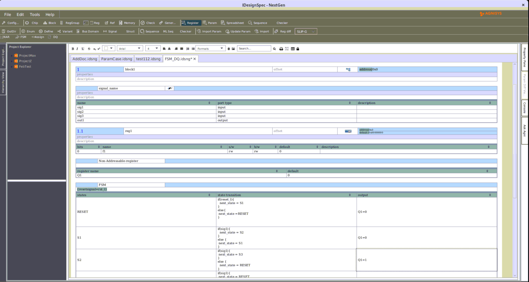
A sample captured specification:


Figure1: Two way conditional next assignment block
In the generated output, the ‘next’ input value expression applied on the field through the property will be evaluated and assigned dynamically on defined specific iterations of repeated parent/ancestor components.
Summary
The property ‘next’ can now accept an expression in the form of strings as its value in a defined register field or even in the field of any specific component among an array of parent/ancestor components to have software events that would act as conditions to update the next value in afield with respect to the value assigned to the property.
Markdown Output
Markdown is a lightweight markup language for creating formatted text using a plain-text editor. IDesignSpec™ is capable of generating Markdown output that reflects the test case in a formatted text file and support in the Markdown viewer.
Markdown has been characterized by an informal specification and a reference implementation for conversion to HTML.
For example:

To create a heading, add number signs (#) in front of a word or phrase. The number of number signs you use should correspond to the heading level. For example, to create a heading level three (<h3>), use three number signs (e.g., ### My Header).
Syntax:
We can format the text into a header using the # symbol
Why Use Markdown?
- Markdown format is portable. Files containing Markdown-formatted text can be opened using virtually any application. In case you don’t like the Markdown application you’re currently using, you can import your Markdown files into another Markdown application.
- Markdown is platform-independent. You can create Markdown-formatted text on any device running any operating system.
To summarize, this is a four-part process:
- Create a Markdown file using a text editor or a dedicated Markdown application. The file should have an .md or .markdown extension.
- Open the Markdown file in a Markdown application.
- Use the Markdown application to convert the Markdown file to an HTML document.
- View the HTML file in a web browser or use the Markdown application to convert it to another file format.
Sample case:
IDSWord input

Markdown Output

SystemRDL input

Excel input

Markdown output

IP-XACT input

Markdown output

Summary
Markdown is a great tool for easily making formatted text files that display across a variety of platforms. It can be extended with extra functionality. This means someone creates another version (or “flavour”) of Markdown.
Markdown’s innate flexibility and potential for use in a wide variety of contexts makes it a very useful output.
Quality Checks For Register Maps
Capturing registers is one of the most tedious and error-prone aspects of designing and implementing an SoC. In the absence of an automated solution, the effort involved in defining a register map grows exponentially, resulting in an increased cost and reduced time to market for the final product.
By convention, a defined register map as a golden specification must pass the battery of all the legal checks, i.e., checks for legal inputs as per the tool to control the output behavior. There are still few areas in the legal scenarios that may lead to errors or areas that are prone to errors in the later stages of the design. These can be avoided by following certain standard practices / best practices to save resources, time, and effort to ensure superior product quality. These practices can ensure avoiding of unnecessary re-spinning of designs due to logical mistakes and functional errors that cause defects at the later stages of the design process causing impact on the entire planned schedule.
IDesignSpec™ (IDS) accepts a register map and follows different defined checks for further processing over the captured register map. These defined checks also include a suite of non-mandatory quality checks for improved quality of a captured register map and to have a future proof design to avoid any issues at the later stages of the design development for smooth flow of the entire design process. They also ensure that designs are easier to debug, optimized for improved performance, simplifies hardware and firmware development, easier to work around defects at the final stages and all by anticipating the impact of the captured register specification on the entire design development cycle.

Figure 1: Flow of all defined checks over a captured register map in the tool
The failure in any of such quality checks results in a detailed and descriptive warning along with a recommendation in the area of compromised quality of the register map. A user may choose to either follow the recommendation or ignore it (if it’s a necessary obligation in the actual design). The continuously growing collection of non-mandatory checks is enabled through a command line switch and one may ignore specific checks among them. The current lot of such quality checks includes:
- Checks for reserved spaces
- Checks for appropriate access for the software interface
- Checks for proper naming conventions
- Checks for uniqueness
- Checks in interrupts
- Checks for parallel addresses
- Checks for alignment
For example:

Figure 2: A legal register map sample
When IDS quality checks are run on this captured legal register map (above Figure 2), the following warnings and recommendations among the lot are currently displayed on the console over appropriate components of the specification:
- Warning on reserved spaces, as compact designs are prone to be backward incompatible when additional components are added at later stages of the design process or on reuse of the design in future projects.
- Warning on access types for the software interface, as it is best recommended to use identical software accesses for all the bits of a register component to avoid confusion in writing and maintaining the code and reduce the risk of introducing errors in the firmware. Also, it is not recommended to use write-only bits as firmware cannot read them and has to maintain a copy to check for functional correctness.
- Warning on discontinuous bit allocation, as adding continuous bits in a big-endian manner ensures firmware can access the bits with shorter hex values, reducing complexity.
IDS ensures that the warnings are descriptive and to the point, and also leaves a pointer to the actual area of compromise in terms of quality in the entire specification.
Summary
These quality checks identified by IDS are based on years of experience with all sorts of register maps. The checks ensure that all stages of the design development cycle are smooth, with shorter and efficient development time, and that the created optimum quality designs are efficient and reusable with no or fewer re-spins due to functional defects or problems.
Future plans include improving the battery of such checks in multiple aspects of the design and allowing users to have custom non-mandatory quality checks with custom detailed warnings to have an efficient user adjustable check process.
SRAM based register implementation
In chips, register bits account for about 10% of the total standard cell area. This is expected to grow multiple fold for next generation chips, so we need to explore alternative methods of register implementation.
Register bits on a chip can be categorized into the following two classes:
1) Dynamic host centric control, status, and debug registers
2) Static algorithm specific hyperparameters
Dynamic registers need HW/SW accessibility all the time and are best suited for FF based register implementation. They account for small portions of registers (<5%) in relation to the total register bits available on the chip.
Static algorithm specific registers are always programmed by SW at boot or in controlled environments, before HW is allowed to consume the data, avoiding simultaneous SW writes and HW reads. They amount to large portions of the total register bits available on the chip.
A typical static register block will have multiple sections, with register bits in each section being an exact replica of other sections as shown in figure below (1.1):

Fig. 1.1 shows a static register block on the AHB bus having 512 repeated sections having 32 registers each.
Fig 1.2 shows the HW interface of the 2 port SRAM with the HW read logic. On read the field data for the required SRAM address will be available on the corresponding field ports.
Register bits (registers) in a section represent a static configuration of the chip at any instance in time. These static register bits are not time sensitive and can be available after a defined (predictable) number of clock cycles for HW reads. HW needs visibility to only one section of register bits at any particular instance in time represented by section address as shown in figure above (1.2)
Register bits implementation in IDesignSpec™ (IDS):

Dynamic registers are mapped to IDS internal registers while the static registers are mapped to memories. The SRAM implementation is outside the IDS Block, but its structure and interface are defined in IDS.
– Internal registers: These are implemented as FF for each register bit. Dynamic registers, which are few, can be implemented as internal registers.
– External registers: The structure for these is defined, but not implemented as FFs, and access ports are provided for use as per application needs. Static registers, which are large in number, can be marked external and implemented as 2 port SRAM with the new IDS property “mapto_dpsram=true”. So a 512 * 32 SRAM can be conceptualized as a repeated external section having 32 registers (each 32-bit wide) and a repeat count of 512. By mapping static registers to external 2-port SRAM 40% of the chip-area can be saved.
Both internal and external registers occupy the same address space.
Summary
The SW interface of SRAM that is both readable and writable is connected to the external IDS interface, while the HW interface which is only readable will have its application logic (required to read the value from the SRAM) outside of the IDS scope while the buffer registers on this end will be defined inside the IDS block.


