Register Field Access Update At Elaboration Time
Introduction
IDesignSpec™ supports a variety of software accesses for defining field bits of a register component. The register bits (fields) can be accessed by the register bus based on the defined access for software read/write transactions. Although the software accesses are generally defined while capturing the register definition itself as static attributes, IDS has been enhanced to support overriding of these accesses at the elaboration time using parameters.
The defined parameters including expression gets resolved dynamically at the elaboration time to decide the final access for the register field bits.
These parameters dynamically update the software access and are used on a field component as shown below-

Here , “$My_val ” is a parameter with the conditional operator for selection of the bus access.
Example Case
A sample captured register specification:

Generated UVM RAL:
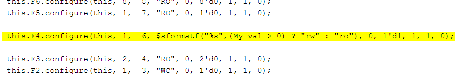
In the above RAL, the “configure” method invoked for the field “F4” uses the expression for resolution of the software access to either “rw” or “ro”.
Conclusion
Overriding parameters at the elaboration time can be done by dynamically changing the software accesses for read/write operations register fields. These parameters can also be similarly used in expressions for overriding the software accesses.
Read/Write on HW Interface and Memory in ISS
Introduction
With the growing complexity of the chip, design/verification engineers spend a hefty amount of time verifying the functionality with many tedious scenarios. While reading/writing design registers with programming/test sequences is a common methodology, often there is a need to write data on some hardware pin or check/read a value from a hardware pin. For example, it is a very common scenario to wait and check for an interrupt signal from a design to get high and then perform some operation.
Another very important aspect of verification involves reading/writing external memories with data. These external memories can also be loaded from a plain text file using the “readmemh” operation.
ISequenceSpec (ISS) has functionality to read/write registers that can involve many other constructs like looping/conditional statements, wait statements, and fork-join blocks for parallelism. ISS now introduces two new capabilities:
- Read/write on hardware interface
- Read/write on external memories
Example of usage of these constructs in ISS:
- Read/write on external memories
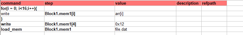
In ISS, memories can be loaded with data in two ways. In the above example, the first write statement depicts that memory ‘mem1’ is loaded with data from an array. The second way is using the “load_mem” command. Using this, memory can be loaded from a plain text file. This plain text file contains memory data that can be loaded into the memory. The format of the plain text file is as follows :
FFFF
ABDD
AABB
FF12
The above data is loaded into a memory with depth 4.
- Read/write on hardware interface
Data to the register address can be written or read through software (bus interface) as well as from the hardware side (hardware ports). These hardware ports are available for the user through a hardware interface (user logic interface).
Hardware interfaces in ISS can be accessed by invoking the “hw_if” construct in the step column of the specification. For each writable field there is a set of field signals that can be accessed from the hardware side for writing, for example, <reg>_<field>_in_enb (input enable for writing data), <reg>_<field>_in (for input write data). For reading register data, the read port “<reg_name>_r” can be used.
In ISS, These hardware ports can be accessed by hw_if.<reg>.<field>.<hardware port>. IDS-NG provides auto completion and provides hints for hw_if.
For accessing interrupt signals, “hw_if.irq” can be used.

Conclusion
With the addition of the new constructs like read/write on a hardware interface and memory, it becomes easier for verification engineers to create correct-by-construction custom sequences for verification of the design.
Multicast/Broadcast Address Decoder
Introduction
There are three ways to decode addresses for the IP blocks. One is the absolute decoding, where all address bits are decoded at each block. This is the default flow. The second way is to do hierarchical decoding in which the address bits are divided into two parts: the MSB part is used to decode the block address and the LSB part is used to decode the register being addressed once the block address (the MSB part) is selected. The third way is to map a slave select to certain address bits in the bus (say, APB) interface thus, providing a special decoder after any bridge (say, AHB-APB) that users will have in their system allowing multicasting/broadcasting while accessing the slaves.
The most significant bits of the bus address space will be decoded in that way by splitting the bus address space into N equally sized areas for the N number of slaves connected to that bus. The user doesn’t have to mix the special decoding logic with “classical” address modes, i.e. for a given bus. Either all slaves are addressed in this direct address-bit to slave select mode or none of them are addressed.
According to the address ranges of the slaves: The lower address bits are used in the classical address mode within each slave (indicated in the diagram below as “xxxx”).
Block Diagram

Figure (i) : Representation of Selector Logic for input {base_address(0x2123_0000), no of slaves(3), component(register) selector bits(13)}
In Figure(i), the slave select addressing might also be done in other areas, e.g., using bits 13 to 15, leading to a slave address space of 13 bits (as bit 0 to 12 are not included in the special decoding mechanism and, thus, are decoded by the slave logic).
SystemRDL Example
property hierarchical_decode { type = string; component = addrmap; };
addrmap Top_chip {
name = “Top_chip Address Map”;
hierarchical_decode= “0x2123_0000,3,13”;
addrmap Block0 {
name = “Block1 Address Map”;
reg Reg1 {
regwidth = 32;
field {
hw = na;
sw = rw;
} F[31:0] = 32’h0;
};
reg Reg2 {
regwidth = 32;
field {
hw = na;
sw = rw;
} F[31:0] = 32’h0;
};
Reg1 Reg1 @0x00;
Reg2 Reg2 @0x04;
};
addrmap Block1 {
name = “Block1 Address Map”;
reg Reg1 {
regwidth = 32;
field {
hw = na;
sw = rw;
} F[31:0] = 32’h0;
};
reg Reg2 {
regwidth = 32;
field {
hw = na;
sw = rw;
} F[31:0] = 32’h0;
};
Reg1 Reg1 @0x00;
Reg2 Reg2 @0x04;
};
addrmap Block2 {
name = “Block2 Address Map”;
reg Reg3 {
regwidth = 32;
field {
hw = na;
sw = rw;
} F[31:0] = 32’h0;
};
reg Reg4 {
regwidth = 32;
field {
hw = na;
sw = rw;
} F[31:0] = 32’h0;
};
Reg3 Reg3 @0x00;
Reg4 Reg4 @0x04;
};
addrmap Block3 {
name = “Block3 Address Map”;
reg Reg5 {
regwidth = 32;
field {
hw = na;
sw = rw;
} F[31:0] = 32’h0;
};
reg Reg6 {
regwidth = 32;
field {
hw = na;
sw = rw;
} F[31:0] = 32’h0;
};
Reg5 Reg5 @0x00;
Reg6 Reg6 @0x04;
};
Block1 Block1 @0x00;
Block2 Block2 @0x08;
Block3 Block3 @0x10;
};
The multicast-mode shall be allowed only on write transactions. A read transaction from a single slave shall be allowed, but a read transaction from a multicast address will report an error on the bus.
When all the selector bits are low/zero or none of the slave is selected, then a default address map (say, placed at 0x0000_0000 to 0x0000_1FFF ) will be selected.
Conclusion
Apart from the traditional absolute decoding of addresses/IPs , slave IPs can also be accessed in a multicast or broadcast manner for software write events through hierarchical decoding. This mechanism allows simultaneous writing on one or more slave addresses, and a default address range is chosen when none of the slaves are selected in a software write event. However, accessing multiple slaves in-case of a software read event reports an error to the bus. Broadcast and multicast is useful in a way that a user need not write the same data on multiple slaves at different times. Instead, it can be written simultaneously.
Git Integration in IDS-NG
Introduction
Git is a fast distributed revision control system for tracking changes in a set of files using repositories, and branches. Its goals include speed, data integrity, and support for distributed, non-linear workflows.
It is the most commonly used version control system, which tracks the changes users make to files, so they have a record of what has been done, and users can revert to their code changes if they ever need to. Git also makes collaboration easier, allowing changes by multiple people to be merged into one source.
In IDS-NG, Git has been integrated for tracking changes in source code during specification development. It is designed for coordinating work among engineers, but it can be used to track changes in any set of files.
Using Git in IDS-NG
Git operations are available in IDS-NG GUI (graphical user interface) such as shown below. So, as shown in the picture, first we have to right click on the project file, then further right click on the versioning option. After that when we hover over the versioning option, then we will initialise the git repository and clone the particular location of the repository.

Users can clone their work environment from Git in IDS-NG and start their developments simultaneously. A Git repository contains all of the project files and the entire revision history.

Created branches can also be managed, i.e, users can delete or checkout the corresponding branch.

After the user merges their code into a branch, files and revision history are pushed to it. After someone else makes changes to a remote repository, users can take (pull) their changes into their local repository. A branch from a remote repository can also be merged.

Pull Requests
Pull requests are a way to discuss changes before merging them into your codebase. Let’s say you’re managing a project. A developer makes changes on a new branch and would like to merge that branch into the master. They can create a pull request to notify you to review their code. You can discuss the changes, and decide if you want to merge it or not.

When we pull them to our local repository we get a merge conflict. Git has a way to handle conflicts, so we can see both sets of changes and decide which we want to keep.
Diff and Merge
In case two files exist for the same specification with variations, then the user can view differences between them and merge both the files according to the desired functionality.
The window will be divided into 3 views:
Head File: Displays the file the user is working on
Target File: Displays the file the user wants to compare with
Merge File: Displays the final file that will be created after the amendments
Note: The merged file actually is the head file, and we can incorporate changes from the target file and head file as depicted below:

Here, the differences are shown in yellow color. We can reach each row one by one by clicking on next, and the red colored cursor will move in accordance to the differences between each file version. We can also navigate through different windows by clicking on the checkbox provided above each test case to be differentiated. We can simplify and easily make changes in the merged file.
Conclusion
IDS-NG now allows users to use Git in the tool itself. Also, IDS-NG is a tool that can differentiate two IDS-NG input files using Git and will show in GUI format. So, the user can take or discard their changes from Origin or Head. Git in IDS-NG also allows users to clone a repository, create a branch, manage branches, commit changes, pull from Origin, and push to Origin from the tool itself.
With this integration, IDS-NG can now be called a true “enterprise class” development environment.
“rwpair” at Field Level
Introduction
Registers are a basic building block of the register space. Each bit or set of bits within the register controls some behavior of the circuit, and is known as a field. Every field has at least two accesses: software (SW) access and hardware (HW) access. The SW access is the access from the host register bus, e.g., AMBA or I2C, and the HW access is the access to the register from the user defined hardware logic.
RW-pair fields are the read only (RO) fields that share the same offset with the write only (WO) fields from the SW side. So, as shown in Figure 1.a., at offset [7:0], there are two fields, FieldA and FieldB, in a register, RegA. FieldA has RO access and FieldB has WO access from the SW side. In IDesignSpec™ (IDS) these read-write pair fields are supported using the “rwpair” property.

Figure 1.a. Representation of RW-pair fields
These pairs of fields come in very handy while creating designs such as UART, I2C, etc. For example, in I2C, to transmit the write data the TX field can be used and to read the received data the RX field can be used. Both fields are exactly at the same position in the memory map and they only differ by their purpose defined by their access. Similarly, in UART, the transmit register is write-only whereas the receive register is read-only. Here, hardware uses the read/write control as a bit, like an address bit, to distinguish between the register accesses.
IDS is capable of not only automatically creating RTL code for such a register but also handles the UVM aspect of it. Since UVM does not have the native ability to handle this field based rwpair, so, in IDS generated RAL, it is accomplished by making an overlap class of the register which resides at the same address but differs in access, as shown in the example below:
SystemRDL Example
property rwpair { type = string; component = reg|field;};
addrmap block {
name = “block Address Map”;
reg RegA {
regwidth = 32;
field {
rwpair = “FldB” ;
hw = w;
sw = r;
} FldA[7:0] = 1’h0;
field {
hw = r;
sw = w;
} FldB[7:0] = 8’h0;
};
RegA RegA @0x0;
};
Generated RAL
Class of RegA, containing readable field, Fld A, with property “rwpair” defined on it:
class block_RegA extends uvm_reg;
. . .
virtual function void build();
this.FldA = uvm_reg_field::type_id::create(“FldA”);
this.FldA.configure(this, 8, 0, “RO”, 0, 8’d0, 1, 1, 0);
endfunction
endclass
Overlap class of RegA for writable field, FldB, which shares same offset with FldA:
class block_RegAoverlap extends uvm_reg;
. . .
// Function : build
virtual function void build();
this.FldB = uvm_reg_field::type_id::create(“FldB”);
this.FldB.configure(this, 8, 0, “WO”, 0, 8’d0, 1, 1, 0);
endfunction
endclass
Inside block class, both the above mentioned classes are added at the same offset in the default map.
virtual function void build();
. . .
default_map.add_reg( RegA, ‘h0, “RW”);
. . .
default_map.add_reg( RegAoverlap, ‘h0, “RW”);
. . .
endfunction
Conclusion
RWpair fields are essential to have in applications where register fields residing at the same address can perform two separate actions based on their accesses without compromising the memory space.


