Newsletter 2022 Q3 Details
Reset values at soft reset in a register field
Introduction
In a digital system, a reset is an action to clear any pending process and brings a system to normal condition or an initial state, usually in a controlled manner.
IDS supports reset conditions to reset any design circuit with two types:
- Soft reset
- Hard reset
The IDS property ‘resetsignal’ is used to add soft reset conditions in the RTL to reset any existing process on a hardware input signal. The property can also be used by combining all the reset signal properties with corresponding default values, as given below:
{resetsignal=rst_sig1:d_val:type:lvl}
where,
‘rst_sig1’ is the soft reset signal, described in the signal table
‘d_val’ is the default value of the corresponding soft reset signal
‘type’ is the type(sync, async ) of the corresponding soft signal
‘lvl’ is the level(low, high) of the corresponding soft signal.
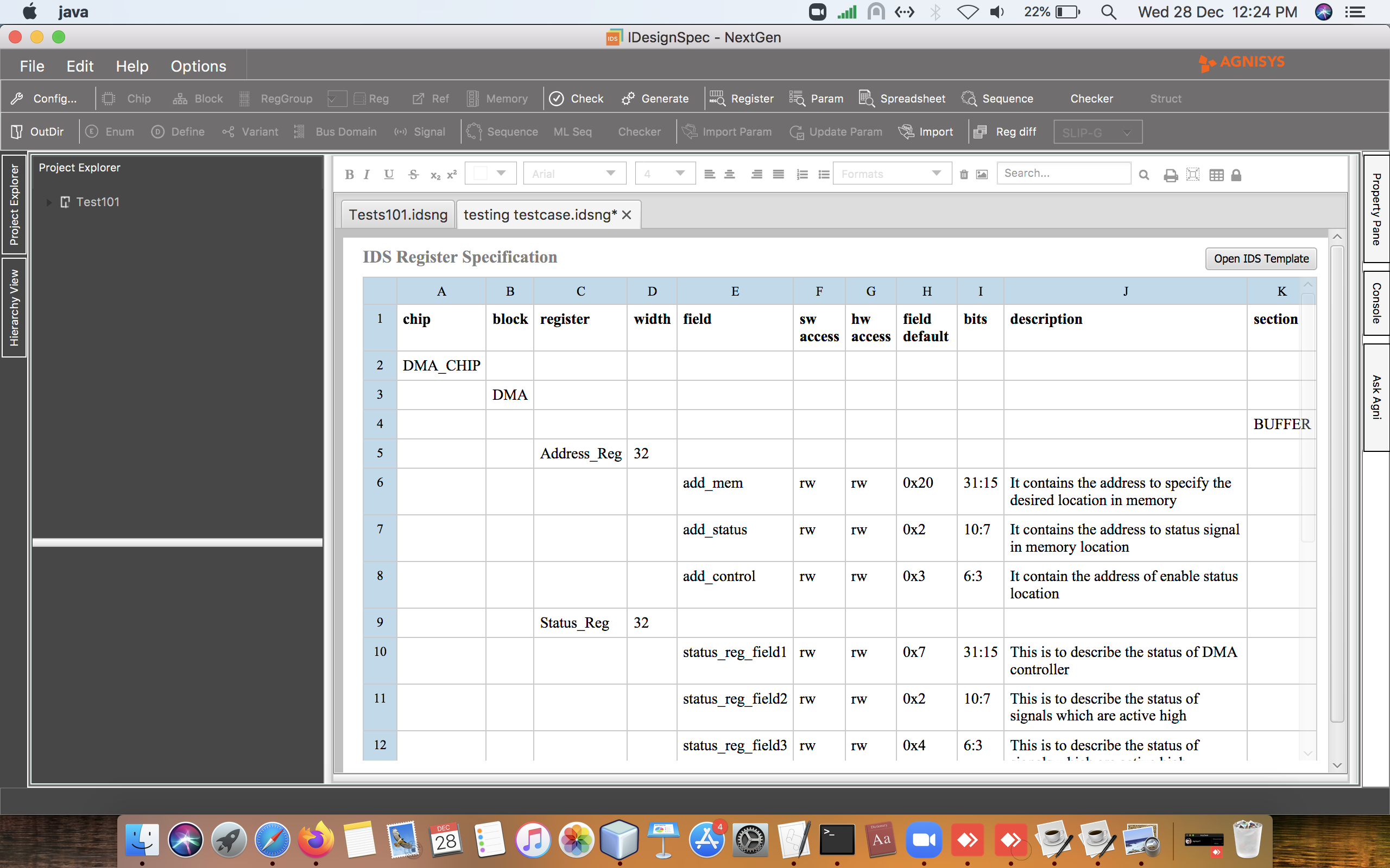
This property has been enhanced to support the following values on a field at reset ‘d_val’ of the above example:
- Any other existing register field value
- Value of any input hardware signal
- Value of a defined parameter in the specification.
Example:

Conclusion:
The property ‘resetsignal’ can accept the default value in the form of parameters, signals, and other existing register field values present in the given register specification. The default value of the field is updated with respect to the value assigned to the property on meeting the soft reset.
Data consistency on adding delays/stages in a bus read/write event
Introduction
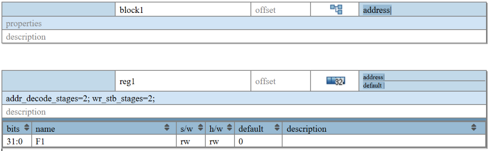
IDesignSpec™ supports properties like wr_stb_stages and addr_decode_stages at the block/register level that gives the flexibility of adding/inserting delays in the read-back path and address decode logic in the generated RTL. The main advantage of introducing such delays at various stages is to meet timing requirements in case the number of registers is large, and the clock frequency is high.
Adding these properties also ensures the consistency of the incoming bus data during the course of the inserted delays. With the delays added in the write strobe stages along with address decode logic (with the properties- wr_stb_stages and addr_decode_stages respectively), the data received is held at the original clock tick until the delayed clock cycle when the address is finally decoded. This is ensured with the help of a default sequential logic that is in sync with the data slicing logic of the properties ‘addr_decode_stages’ and ‘wr_stb_stages’ which must be used together with the same property value to maintain data consistency.

Fig A: wave-diagram of data transmission on adding delays
Example:
Output Verilog
. . .
. . .
// wr_data Stages
always @(posedge clk) begin
if (!reset_l)
begin
Reg1_wr_data0 <= ‘b0;
Reg1_wr_data1 <= ‘b0;
end
else
begin
Reg1_wr_data0 <= wr_data;
Reg1_wr_data1 <= Reg1_wr_data0;
end
end//end always
. . .
Conclusion:
Adding delays/stages in the data transmission path is ensured with the consistency of data received from the register bus interface which is synchronized with the used delay stages properties (address decode stages, write strobe stages) resulting in a change in register data with the updated software data when the valid address is finally decoded.
Integration of 3rd party RTL in IDS-aggregation logic
Introduction
IDS-generated aggregation logic is used to control the slave, based on the input from the master, where it selects which block will operate. The generated aggregation logic is for a chip element which selects each child block based on the addresses and other factors from the master.
IDS generated RTL blocks have parameterized offsets with a default offset of ‘0’, which are overridden on their instance by the upper chip module for decoding of the actual registers with respect to the address map. And the generated aggregation logic selects and decodes these blocks on the basis of their absolute addresses.
IDS generated assignments to prdata, pready, and pslverr do not contain the muxing of active slave selection logic (i.e., block_name>_psel) and generated aggregation logic has *pready as ANDed logic w.r.t the pready signal of the IDS generated blocks where it is assumed to be always ready to be accessed.
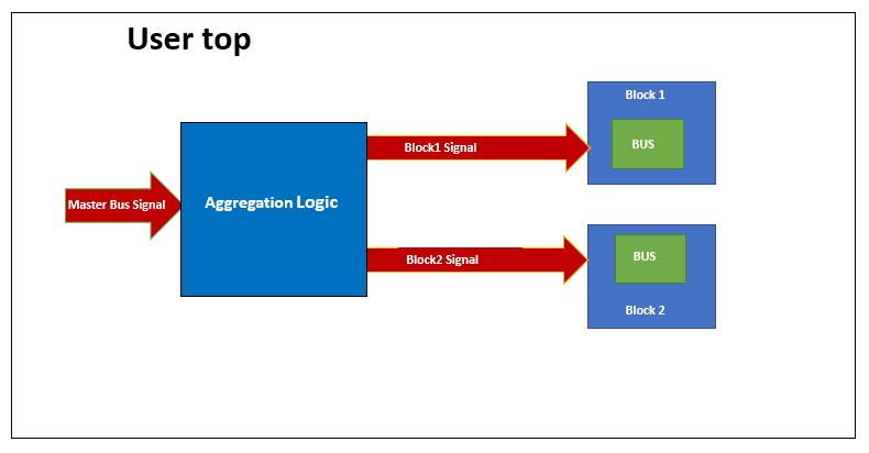
Figure-1: Basic block building in IDS
Example of usage of 3rd party RTL:
IDS-NG Input

System RDL Input
`ifndef IDS_UDP
property aggregation_logic {type = string; component = addrmap; };
property aggr_block_offset {type =string; component = addrmap; };
`endif
// chip : chip_top
addrmap chip_top {
name = “chip_top Address Map”;
aggregation_logic = “third_party”;
addrmap elite_block1 {
name = “elite_block1 Address Map”;
aggr_block_offset = “third_party”;
reg reg_ram {
regwidth = 32;
field {
hw = rw;
sw = rw;
} f1[31:0] = 32’h0;
};
reg_ram reg_ram @0x0;
};
addrmap ace_block2 {
name = “ace_block2 Address Map”;
aggr_block_offset = “third_party”;
reg reg_impact {
regwidth = 32;
field {
hw = rw;
sw = rw;
} f2[31:0] = 32’h0;
};
reg_impact reg_impact @0x0;
};
elite_block1 elite_block1 @0x0;
ace_block2 ace_block2 @0x4;
};
In the above example, there is a top component “chip_top ” having two blocks/IPs, “elite_block1″ and “ace_block2″. The “elite_block1” and “ace_block2” are third party RTL IPs/Blocks with the property “aggr_block_offset=third_party” applied. Whenever aggregation logic selects such a block , it will reduce its offset from the paddr before aggregating it to the block. The top component “chip_top ” has the property “aggregation_logic = third_party”, which will be used on the chip element to get an aggregator which contains the signals (prdata, pready, and pslverr) assignment with the active slave selection logic.
RTL output impact
. . .
assign prdata = ({32{elite_block1_ids_psel}} & elite_block1_ids_prdata) | ({32{ace_block2_ids_psel}} & ace_block2_ids_prdata);
assign pready = (elite_block1_ids_psel & elite_block1_ids_pready) | (ace_block2_ids_psel & ace_block2_ids_pready);
assign pslverr = invalid_address | (elite_block1_ids_psel & elite_block1_ids_pslverr) | (ace_block2_ids_psel & ace_block2_ids_pslverr);
. . .
Conclusion:
IDS supports third party RTL integration with IDS aggregation logic. By using the above properties, IDS can modify the aggregation logic in the case of third party RTL integration.
Plugin Environment support in IDS-NG
Introduction
IDS-NG is an Integrated Development System for automating Spec to SoC flow allowing Design, Verification, Validation, Firmware, and Documentation. It provides users the flexibility and facility to customize it as per their requirements
IDS provides the functionalities to include third-party applications as plugins for custom generators, custom DRCs with their enable/disable through GUI, input processing (table format), etc. Users can extend the IDS input format and their requirements to support the user-defined templates and tables. Also, users can plugin their own generator in the IDS to generate their specific outputs.
Once the register specification is captured. Designers work on creating a synthesizable application logic layer for the intended functionality using these addressable hardware registers. Creating this application logic layer often consists of using various design constructs. There is a need to create an automation technique to overcome the manual work of creating Application Logic with the help of the Complete-IP solution.
- The creation of a Synthesizable RTL Application logic layer and a UVM Prediction model through some predefined templates.
- These templates capture all the necessary information required to build up an application logic. These includes:
- Finite State Machines
- Custom flip flops
- Continuous Assignments
- The Complete IP templates come under an additional plugin that needs to be installed on IDS-NG.
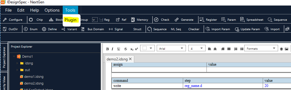
Ways to Use plugin Environment in IDS-NG
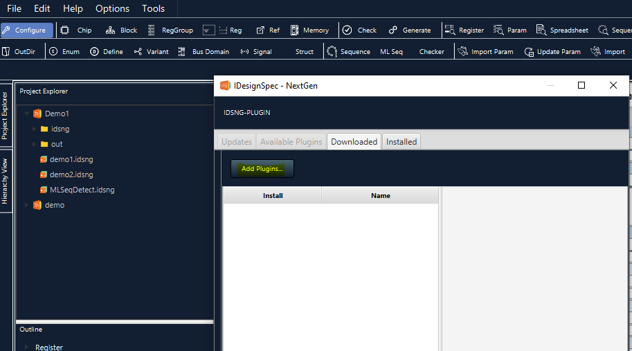
In order to use the plugin feature in IDS-NG users must run IDS-NG as administrators and have a JSON file with defined specs. Then clicking on the Tools menu and clicking on the Plugin option, a new pop-up window opens. Clicking the “Add Plugins” button, a new window opens, choose the JSON input file and select that file. It will be required to restart IDS-NG for changes to be applied and custom template buttons will be added to the Custom Toolbar row. Each button has different functionalities for inserting templates.
Conclusion
IDS-NG will allow users to plug in their own generator in the IDS-NG to generate their specific output. Users can create their own environment as well as particular specifications and outputs. Features like adding a plugin or opening/updating a plugin are available through which a new toolbar row can be added with a button named based on the data provided by the users.