The IC Designer’s Guide to Automated Specification of Design, Verification, and Validation for Better Products

Content
- Overview
- Specifications Are Ambiguous
- Specifications Are Ambiguous
- Specifications Change Constantly
- Specifications Cause Bugs
- Specification Automation Is the Answer
- Register Automation Is Widely Used
- Generating RTL Is Not Enough
- More than Simple Registers Are Required
- More than Registers Must Be Automated
- Specification Changes Must Be Automated
- The Agnisys Difference
- Conclusion
Overview
Every IC engineer and engineering manager involved in complex system-on-chip (SoC) and hardware intellectual property (IP) development knows that getting the design functionally correct is an epic challenge. Every step of the process—design, verification, embedded software programming, emulation, prototyping, pre-silicon validation, post-silicon validation in the bringup lab, and end-user documentation—has risks despite consuming huge amounts of human and compute resources. For an ASIC or full-custom chip, the costs for a silicon turn to fix bugs are staggering and the delay in time to market (TTM) can compromise product success. Although FPGA errors can be fixed without a respin, reprogramming in the field is usually impossible, so bug escapes are still very expensive.
There are multiple causes for designs being wrong, but some of the most common are related to the design specifications. Traditional specifications are written manually in natural language , updated manually, and communicated to the development team in an uncoordinated manner. This paper details the negative effects of this approach, examines why some attempts to fix the situation are insufficient, and presents a proven solution: specification automation. Every SoC and IP project benefits from adopting this solution, greatly reducing the chance of a chip turn due to functional errors and shortening TTM.
Specifications Are Ambiguous
Every IC design, like any engineering project, starts with a specification. None of the development teams can do their job without knowing what they are supposed to create. For an engineer, the more precise the specification, the more likely the design will match its intent. Historically, specifications have been written in a natural language such as English, first as paper documents and then as online files. Natural language is inherently imprecise and ambiguous, subject to inconsistent interpretation by different teams and even by individual engineers within a single team.
For example, the hardware-software interface (HSI), which defines how code interacts with the design, is a key part of most SoC and IP specifications. If the register transfer level (RTL) designers and the embedded programmers have divergent interpretations of the HSI, the system will not operate as intended. Even if a software change can partially compensate for a hardware error without a chip turn, performance and functionality are likely to be reduced. This type of project challenge is inevitable with traditional design specifications.
Specifications Change Constantly
Even if the initial specifications were somehow perfect and unambiguous, the problem would not be solved. Specifications change many times over the course of a project. Market conditions and competitive pressures might mandate new features. Feedback from the design and implementation teams often require changes so that the design can meet its power, performance, and area (PPA) goals, and sometimes these changes ripple all the way back to the specifications.
Every time that a specification changes, the designers update their RTL code, the verification team updates their testbench and tests, the programmers revise their embedded code, the entire hardware-software design must be revalidated, and the technical writers must ensure that the documentation is in sync. The specification changes may not be communicated consistently to all teams, and every time there is a renewed risk of different interpretations by different teams. The waterfall effect, as shown in Figure 1, increases project costs and delays TTM.
Complete the form to download
your copy of this eBook.

Specifications Cause Bugs
Precise specification of hardware and software has been an academic pursuit for many decades, with mixed results. The ultimate vision is that formal specifications can be used for pushbutton generation of entire chips and the complete software stacks to operate them, with tradeoffs between the hardware and software depending upon target technology, end application, and user-specified constraints. This lofty goal remains a vision but, for many portions of the design, specification automation is a reality today.
The most widely adopted form of executable specification is for the registers in the design, especially those that define the HSI. Listing all the register groups, individual registers, and fields in the registers is amenable to precise specification. In fact, several standards such as SystemRDL have been defined for just this purpose. Adopting one of these formats eliminates ambiguity and ensures that all teams on an SoC or IP project will interpret the registers the same. However, if all the project files must be generated manually, this still consumes a lot of precious engineering time and runs the risk of human error in the creation of the RTL design, embedded code, verification and validation files, and documentation. This is the motivation for the second conclusion that the specification must be executable.
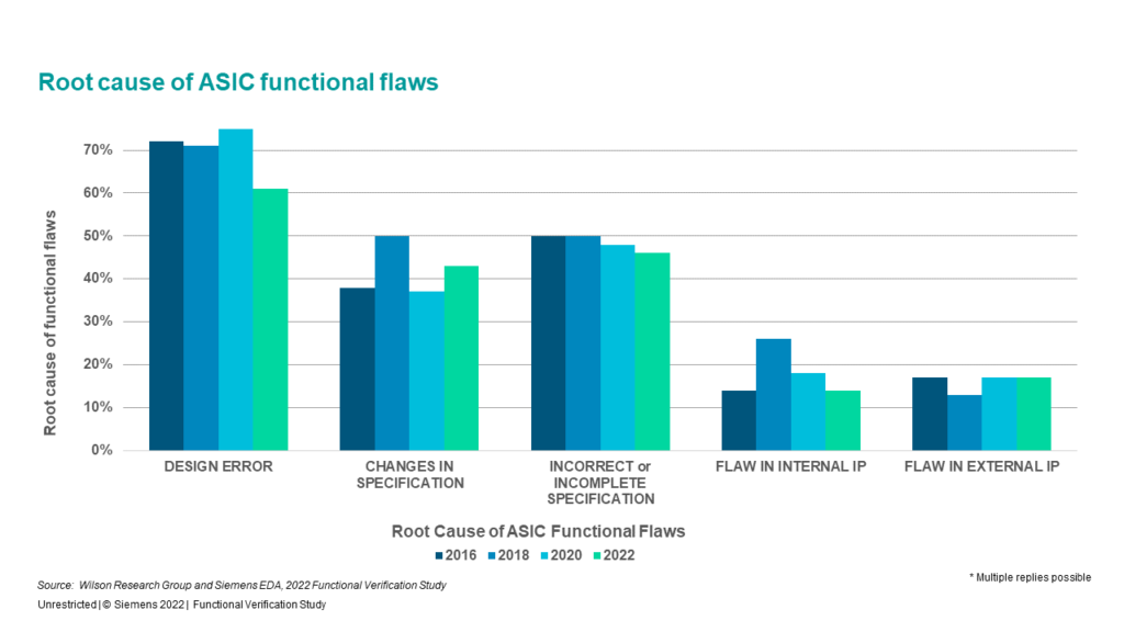
The impact of imprecise specifications and frequent changes is well documented. The widely respected biannual Functional Verification Study from Wilson Research Group and Siemens EDA offers compelling evidence. Every survey in the past few years has shown that inaccurate specifications, incomplete specifications, and changes to specifications are some of the primary causes for functional errors in IC designs. Figure 2 shows the results for ASICs and Figure 3 displays similar results for FPGAs.

Specification Automation Is the Answer

- Specifications must be written in a precise, non-ambiguous format
- The specification format must be executable so that many types of project files can be generated automatically
- Every specification change must trigger a re-generation so that the files remain in sync
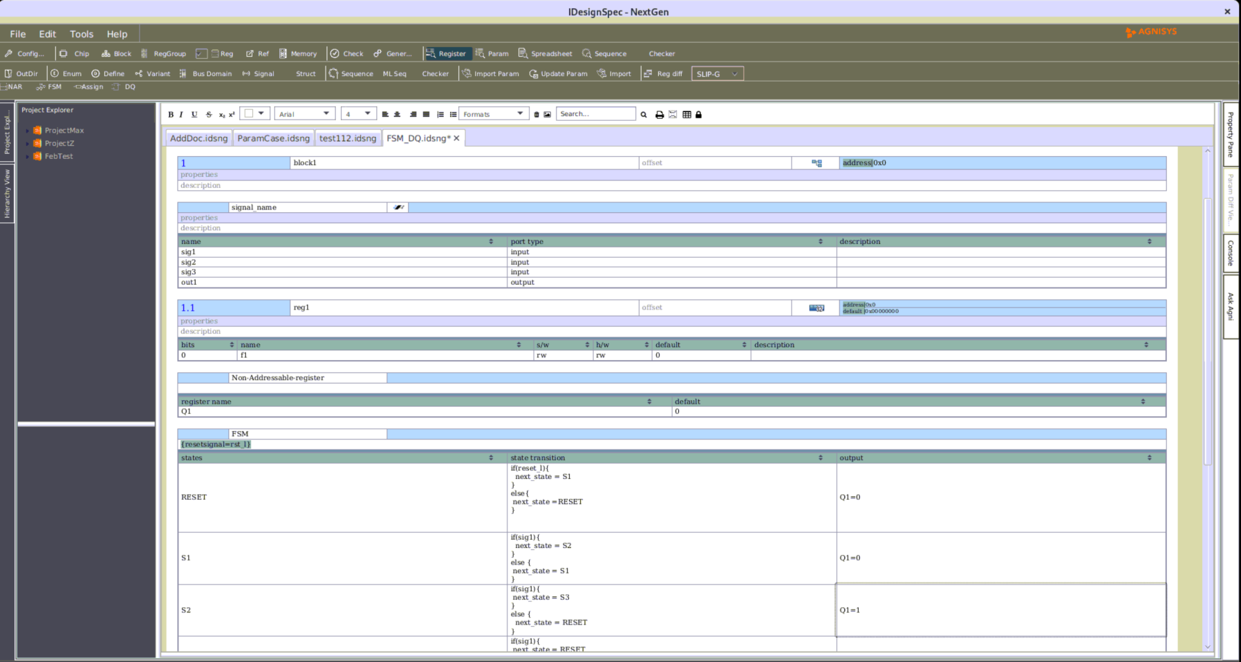
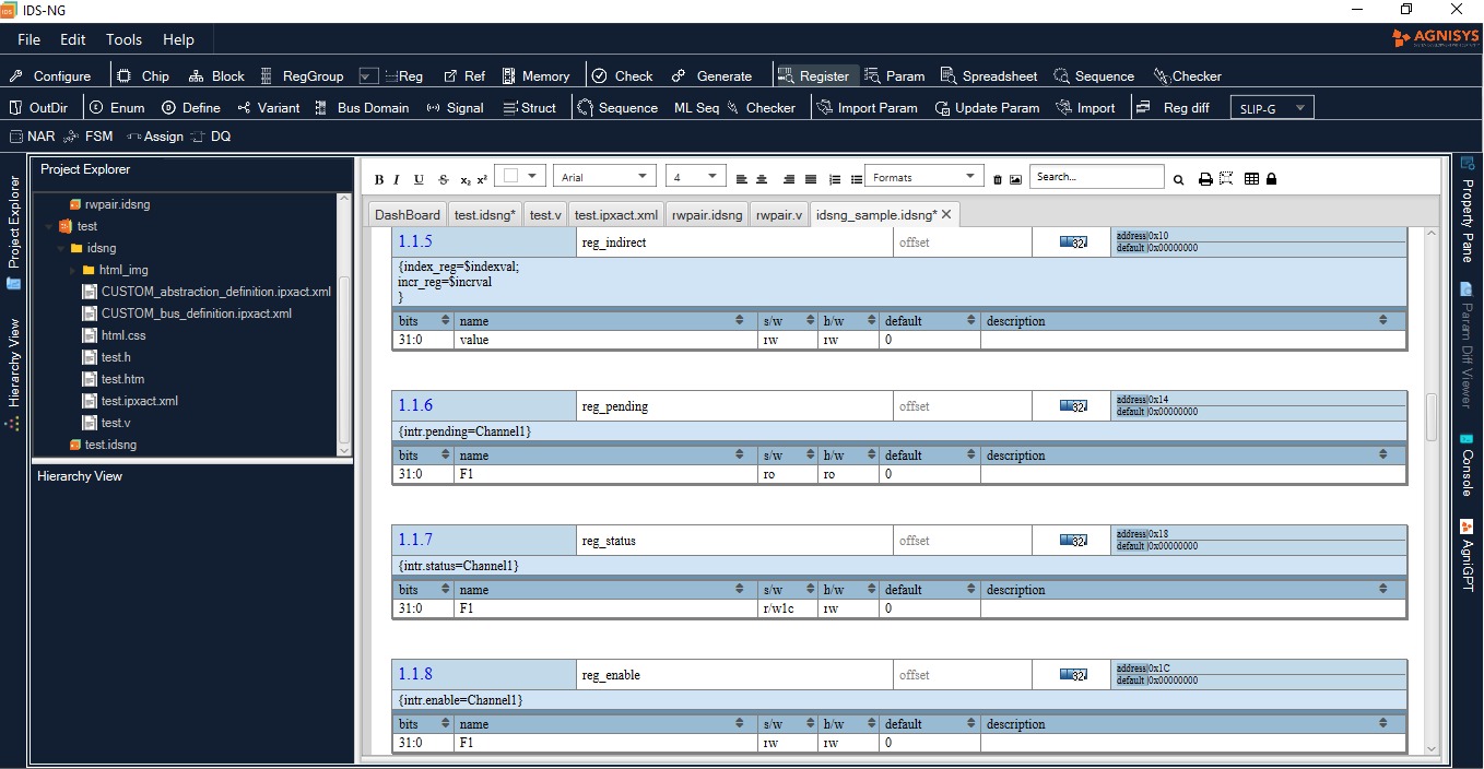
Precise specification of hardware and software has been an academic pursuit for many decades, with mixed results. The ultimate vision is that formal specifications can be used for pushbutton generation of entire chips and the complete software stacks to operate them, with tradeoffs between the hardware and software depending upon target technology, end application, and user-specified constraints. This lofty goal remains a vision but, for many portions of the design, specification automation is a reality today.
The most widely adopted form of executable specification is for the registers in the design, especially those that define the HSI. Listing all the register groups, individual registers, and fields in the registers is amenable to precise specification. In fact, several standards such as SystemRDL have been defined for just this purpose. Adopting one of these formats eliminates ambiguity and ensures that all teams on an SoC or IP project will interpret the registers the same. However, if all the project files must be generated manually, this still consumes a lot of precious engineering time and runs the risk of human error in the creation of the RTL design, embedded code, verification and validation files, and documentation. This is the motivation for the second conclusion that the specification must be executable.
Register Automation Is Widely Used
For register definitions, tools have existed for a couple of decades to generate RTL code that matches the specification. A basic solution to register automation is not, by itself, very challenging to create. In fact, some design teams have chosen to implement their own in-house tool for this purpose. This do-it-yourself (DIY) approach has many issues:
- It consumes engineering time and resources that can be put to better use creating product differentiators
- Internally developed tools require maintenance and user support, so they are on ongoing expense
- Significant additional resources are required to update the tools as standards evolve
- Internal tools lack the wide exposure to many types of designs and the extensive regression test suite of commercial products
- One bug in an internal tool can have a negative cost and schedule impact on every SoC and IP project

Generating RTL Is Not Enough
Internally developed tools, shareware, and most commercial solutions for register automation fall far short of what is needed for a full specification automation solution. For a start, generating just the RTL design does not provide a scalable or complete solution . The design must be verified, programmed, validated, and documented, so it is critical to automatically generate as many of the required files as possible.

Corresponding predefined and custom sequences must also be automatically generated in C/C++ to test the registers from the software side of the HSI and to validate that the entire hardware-software design works properly. This includes generating a hybrid UVM-C/C++ environment for pre-silicon validation. The generated software sequences must be able to run on the embedded processors in emulation, prototyping, and even on actual silicon in the bring-up lab for post-silicon validation. In addition, the programmers often incorporate these sequences into their production embedded code or drivers. This accelerates development of software as well as the RTL design.
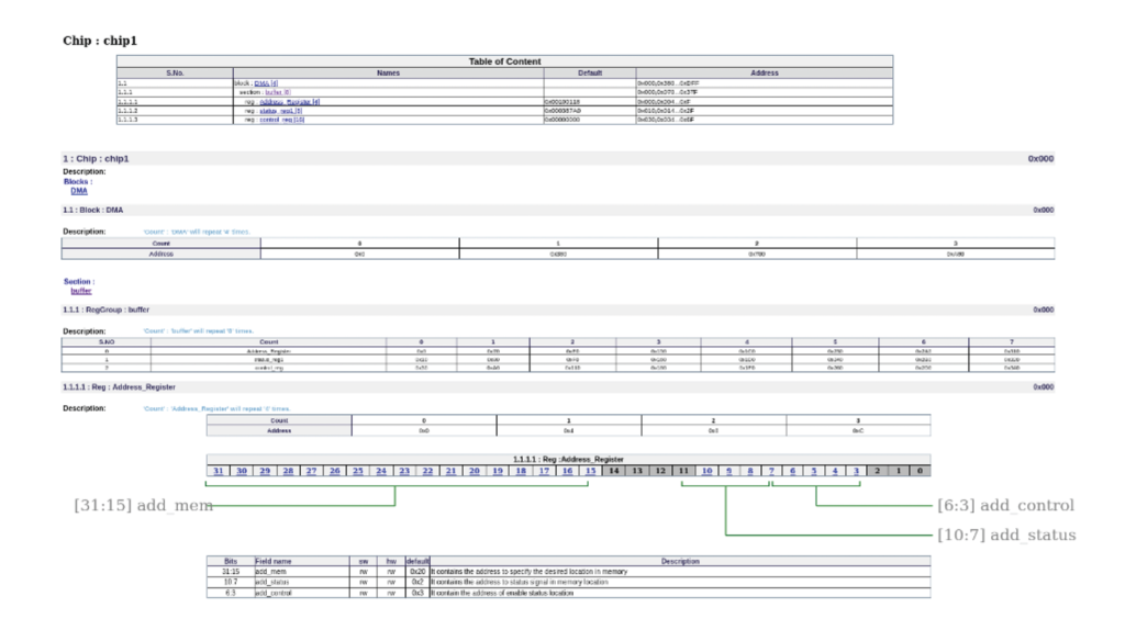
For verification using formal methods, the register automation solution must generate SystemVerilog Assertions (SVA) that can be used to prove the correctness of the design. Most IC projects today rely on a combination of formal verification, simulation, emulation, and FPGA prototyping, so it is important to support and enable all these methods. Any automation tool must also be able to generate high-quality documentation of the registers suitable for inclusion in user manuals, as shown in Figure 4.
More than Simple Registers Are Required
The specification format, generated RTL code, and generated sequences must accommodate memories as well as registers and a wide range of special register types. These include indirect, indexed, read-only/write-only, alias, lock, shadow, FIFO, buffer, interrupt, counter, paged, virtual, external, and read/write pairs. This list, which grows all the time as designs continue to get more complex, is not supported by shareware tools or most commercial products. It would take an enormous investment for in-house tools to handle this list, since the sequences are very different for the different special register types.
In addition, generating registers is not enough. The registers are accessible to software via the HSI over some sort of processor or peripheral bus, so a complete register automation solution must generate the bus interface RTL logic as well. Standard buses supported must include AHB, APB, AXI, AXI-Lite, and TileLink. It must also be possible to accommodate proprietary bus protocols as specified by the user. In most cases, this interface and the custom design blocks will be on independent, asynchronous clocks. The generated RTL code must include the necessary structures to synchronize signals across each clock domain crossing (CDC) boundary .
Users developing designs for safety-critical applications such as embedded medical devices and self-driving cars have further requirements. Safety standards such as ISO 26262 and IEC 61508 mandate inclusion of safety mechanisms that can detect faults in the field and take appropriate actions for recovery. The specification automation solution must generate the safety logic to detect and report faults , including the following techniques:
- Parity bit to detect a changed value
- Cyclic redundancy check (CRC) to detect a changed value
- Single error correction double error detection (SECDED) to both detect and correct a changed value
- Triple modular redundancy (TMR) so that two correct values will “outvote” an incorrect value
More than Registers Must Be Automated
A true specification automation solution goes well beyond registers and memories. In addition to the standard buses, users want to be able to use standard IP design blocks such as AES, DMA, GPIO, I2C, I2S, PIC, PWM, SPU, Timer, and UART. There are shareware RTL files available for many of these blocks, but fixed designs are rarely usable without extensive work. What SoC designers need is not a library of IP blocks, but a library of IP generators. That way, each instantiation of a block can be configured for such attributes as bus width, number of ports, optional functionality defined in the standard, PPA tradeoffs, and user extensions. Further, using a generator may make it feasible to generate outputs for simulation and formal verification, UVM and C/C++ sequences, and user documentation.
Custom blocks in the design contain more than registers and memories, and designers would like to automatically generate as much of their RTL code as possible. This is an area of active development in the industry, but a complete specification automation solution today must be able to generate at least finite state machines (FSMs), data paths, arithmetic elements, and signals from executable specifications. As with standard IP blocks, it may also be possible to generate verification, validation, and documentation files.
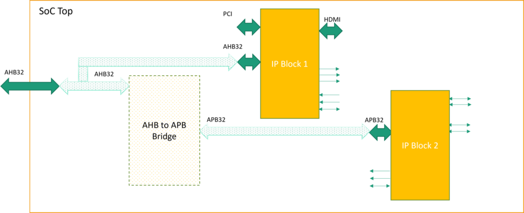
Hooking up thousands of standard and customer blocks into a top-level SoC design is another task that benefits from specification automation. This task sounds easy, but doing it manually is tedious and certain to result in mistakes. The interconnect changes countless times during a project, and every manual update is a new chance for errors. A complete specification automation solution must provide an executable format for defining chip hookup and generate a top-level RTL file as well as SVA to formally verify the connections. It must also generate the RTL code for any necessary “plumbing” components such as bus multiplexors, aggregators, and bridges, as shown in Figure 5.
Specification Changes Must Be Automated
All the generation capabilities beyond registers can also be integrated with project management tools and triggered automatically when a specification changes.
If the designers change their mind about a standard IP block, modify a custom IP block, or need to re-connect the SoC, they simply modify the specification as required. The automation solution recognizes the change and re-generates all affected design, software, verification, validation, and documentation files. This maintains accuracy and consistency, keeping all project teams in sync.
Clearly, there is a huge difference between a simple register automation tool and a complete commercial specification automation solution supported by a team of experts. Figure 6 summarizes the capabilities that are essential in such a solution.
The Agnisys Difference
No in-house tool, shareware project, or limited register automation tool provides the full range of capabilities required for a complete specification verification solution. Only the IDesignSpec™ Suite from Agnisys satisfies the requirements discussed in this paper. Other solutions cannot handle the full range of special registers, automate sequences, support custom sequences and custom IP blocks, hook up IP blocks, or generate verification, validation, and documentation files. For more than fifteen years, Agnisys has been the industry leader in specification automation and has pioneered all the key innovations and refinements.
The Agnisys software products and development flow are certified by the internationally known testing and inspection organization TÜV SÜD as meeting the stringent tool qualification criteria defined by the ISO 26262 and IEC 61508 functional safety standards. Developers of safety-critical designs do not need to do any work to qualify or certify the Agnisys products used in their flows, saving them significant time and money when their customers require standards compliance.

As a company dedicated to specification automation, Agnisys is extremely responsive and views its customers as partners in product evolution. The worldwide applications engineering team is located wherever users are, to provide rapid responses and timely support. The website includes a customer portal with software downloads, product and technology training, and tracking of customer-specific issues. Users can choose Agnisys secure in the knowledge that they are benefitting from the industry’s most advanced technology and best support. To learn more, read “How Agnisys Eliminates Redundancies in Semiconductor Design, Verification, and Validation.”
Conclusion
As shown in Figure 7, the Agnisys solution benefits every team on the SoC or IP project :
- Architects specifying the HSI and other parts of the design
- RTL hardware designers
- Programmers developing embedded firmware and drivers
- Verification engineers using simulation and formal technologies
- Engineers running pre-silicon validation with emulations and prototypes
- Bringup engineers performing post-silicon validation using actual chips
- Technical writers developing end-user documentation
- CAD engineers overseeing and automating the development process

